TRANSMITTER INSTALLATION
Transmitter Location
Mount the enclosure in an area that is convenient for servicing and calibration or for observing the LCD readout.
1. Locate the transmitter within the length of the transducer cables supplied or exchange the cable for one that is of
proper length.
2. Mount the transmitter in a location:
• Where little vibration exists.
• That is protected from corrosive fluids.
• That is within the transmitters ambient temperature limits –40 …185° F (–40…85° C).
• That is out of direct sunlight. Direct sunlight may increase transmitter temperature to above the maximum limit.
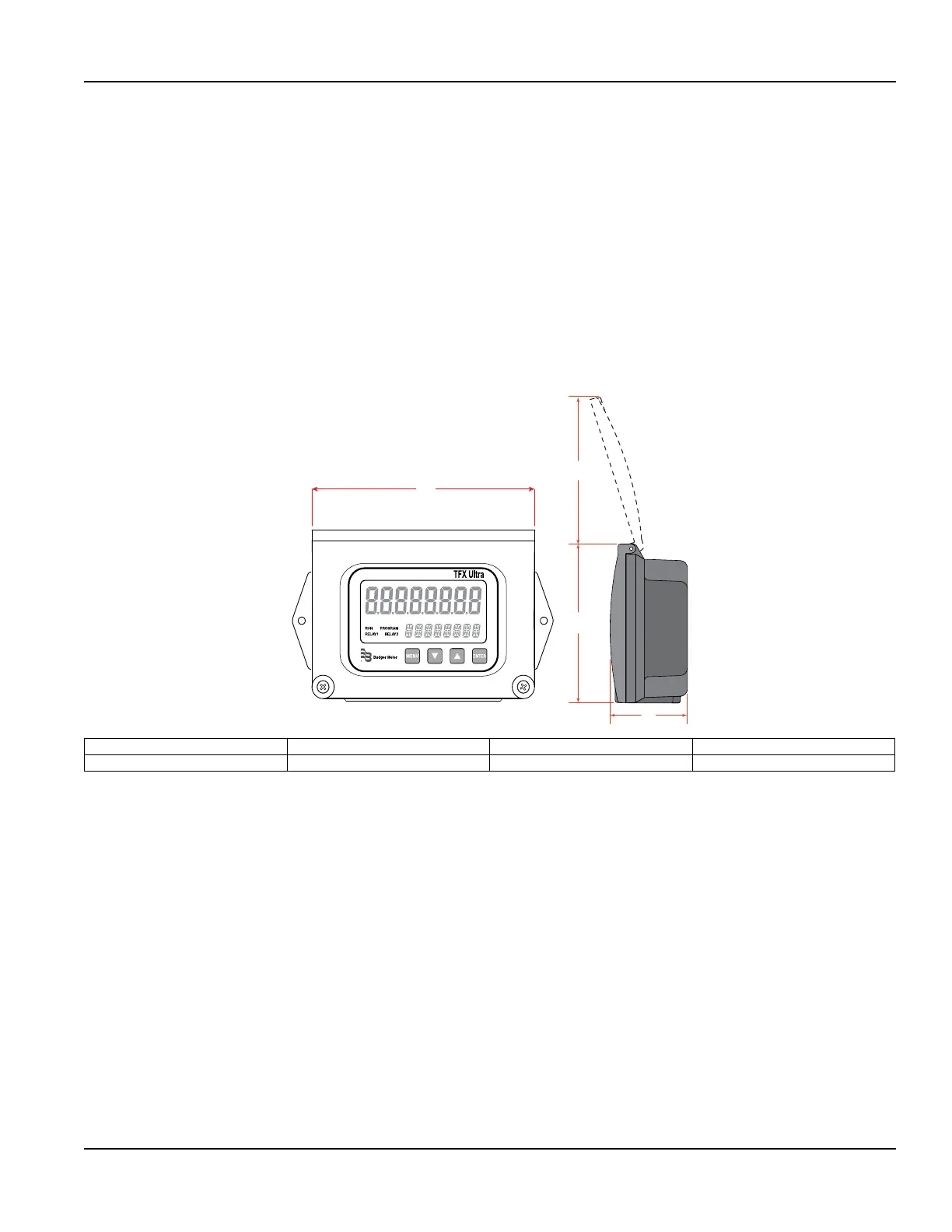
C
B
D
A
A B C D
6.00 in. (152.4 mm) 4.20 in. (106.7 mm) 4.32 in. (109.7 mm) 2.06 in. (52.3 mm)
Figure 2: Transmitter enclosure dimensions
3. Refer to Figure 3 for enclosure and mounting dimension details. Allow enough room for door swing, maintenance and
conduit entrances. Secure the enclosure to a at surface with two fasteners.
4. Use conduit holes where cables enter the enclosure from the bottom. Use plugs to seal any holes that are not used for
cable entry. An optional cable gland kit (part number D010-1100-000 ) is available for inserting the transducer and power
cables. Order the kit directly from the manufacturer.
OTE:N Use NEMA 4 (IP-65) rated fittings/plugs to maintain the watertight integrity of the enclosure. Generally, the right
conduit hole (viewed from front) is used for power, the left conduit hole for transducer connections, and the center
hole is used for I/O wiring.
Transmitter Installation
Page 11 May 2016 TTM-UM-00136-EN-06
 Loading...
