1000 Ω
1000 Ω
SUPPLY LINE
RTD #1
RETURN LINE
RTD #2
BACK OF
CONNECTOR
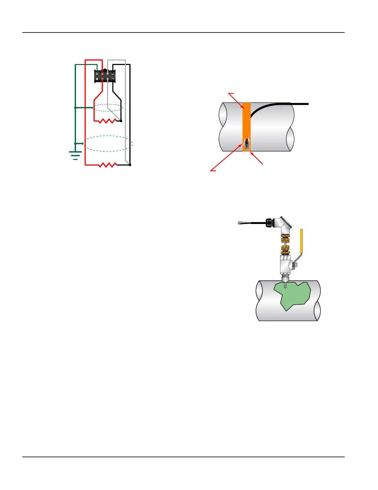
Figure 34: RTD schematic
MINCO
Clean RTD Mounting
Area to Bare Metal Surface
Heat Sink
Compound
Heat Tape
Figure 35: Surface mount RTD installation
Installing Insertion (Wetted) RTDs
Insertion RTDs are typically installed through 1/4 inch (6 mm) compression
fittings and isolation ball valves.
1. Insert the RTD suciently into the ow stream such that a minimum of
1/4 inch (6 mm) of the probe tip extends into the pipe diameter.
RTDs should be mounted within ±45 degrees of the side of a horizontal
pipe. On vertical pipes, the orientation is not critical.
2. Route the RTD cables back to the transmitter and secure the cable so it
will not be pulled on or abraded inadvertently.
If the cables are not long enough to reach the transmitter, route the
cables to an electrical junction box and add cable from that point. Use
three-wire shielded cable, such as Belden® 9939 or equal.
OTE:N Adding cable adds to the resistance the transmitter reads and may
have an effect on absolute accuracy. If cable is added, add the
same length to both RTDs to minimize errors due to changes in
cable resistance.
Figure 36: Insertion style RTD installation
Wiring RTDs to the Transmitter
After the RTDs have been mounted to the pipe:
1. Route the cable back to the transmitter through the middle hole in the enclosure.
2. Insert the RTD connector into the mating connector on the circuit board. Be sure that the alignment tab on the RTD cable
is up.
Heat Flow for Energy Model Only
Page 32 May 2016TTM-UM-00136-EN-06

 Loading...