Select a Mounting Conguration
The transmitter can be used with six different transducer types: DTTR, DTTN, DTTL, DTTH DTTS and DTTC. Meters that use
the DTTR, DTTN, DTTL or DTTH, transducer sets consist of two separate sensors that function as both ultrasonic transmitters
and receivers. These transducers are clamped on the outside of a closed pipe at a specific distance from each other. DTTS
and DTTC transducers integrate both the transmitter and receiver into one assembly that fixes the separation of the
piezoelectric crystals.
The DTTR, DTTN, DTTL and DTTH transducers can be mounted in:
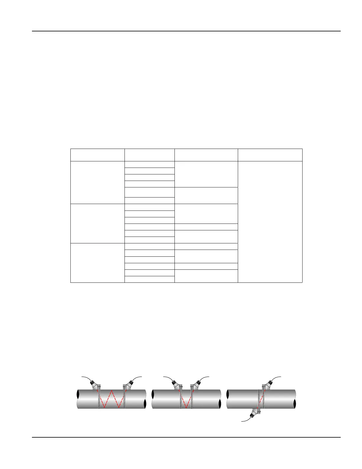
• W-Mount where the sound traverses the pipe four times. This mounting method produces the best relative travel time
values but the weakest signal strength.
• V-Mount where the sound traverses the pipe twice. V-Mount is a compromise between travel time and signal strength.
• Z-Mount where the transducers are mounted on opposite sides of the pipe and the sound crosses the pipe once. Z-Mount
will yield the best signal strength but the smallest relative travel time.
Transducer Mounting
Configuration
Pipe Material Pipe Size Liquid Composition
W-Mount
Plastic (all types)
2…4 in. (50…100 mm)
Low TSS (Total Suspended
Solids); non-aerated
Carbon Steel
Stainless Steel
Copper
Ductile Iron
Not recommended
Cast Iron
V-Mount
Plastic (all types)
4…12 in. (100…300 mm)Carbon Steel
Stainless Steel
Copper 4…30 in. (100…750 mm)
Ductile Iron
2…12 in. (50…300 mm)
Cast Iron
Z-Mount
Plastic (all types) > 30 in. (> 750 mm)
Carbon Steel
> 12 in. (> 300 mm)
Stainless Steel
Copper > 30 in. (> 750 mm)
Ductile Iron
> 12 in. (> 300 mm)
Cast Iron
Table 2: Transducer mounting modes for DTTR, DTTN, DTTL and DTTH
The transducers can be mounted in V-Mount where the sound transverses the pipe two times, W-Mount where the sound
transverses the pipe four times, or in Z-Mount where the transducers are mounted on opposite sides of the pipe and the
sound crosses the pipe once. The selection of mounting method is based on pipe and liquid characteristics which both have
an effect on how much signal is generated. The transmitter operates by alternately transmitting and receiving a frequency
modulated burst of sound energy between the two transducers and measuring the time interval that it takes for sound to
travel between the two transducers. The difference in the time interval measured is directly related to the velocity of the liquid
in the pipe.
The appropriate mounting configuration is based on pipe and liquid characteristics. Selecting the proper transducer
mounting method is an iterative process. Table 2 contains recommended mounting configurations for common applications.
These recommended configurations may need to be modified for specific applications if such things as aeration, suspended
solids, out-of-round piping or poor piping conditions are present.
TOP VIEW
OF PIPE
W-Mount V-Mount Z-Mount
TOP VIEW
OF PIPE
TOP VIEW
OF PIPE
Figure 8: Transducer mounting modes for DTTR, DTTN, DTTL and DTTH
Transducer Installation
Page 17 May 2016 TTM-UM-00136-EN-06

 Loading...