Service Menu (SER)
The SER MENU menu allows access to transmitter setup values that may need revision due to application-specific conditions
and information valuable in troubleshooting.
Parameter Meaning Description
SSPD MPS
Liquid sound
speed in meters
per second,
reported by the
firmware
The transmitter performs an actual speed-of-sound calculation for the liquid it is measuring. The calculation varies with
temperature, pressure and fluid composition.
The transmitter compensates for fluid sound speeds that vary within a window of ± 10% of the liquid specified in the BSC
MENU. If this range is exceeded, error code 0011 appears on the display and you must correct the sound speed entry.
The value indicated in SSPD measurement should be within 10% of the value specified in the BSC MENU item FLUID SS. (The
SSPD value itself cannot be edited.) If the actual measured value is significantly different (> ± 10%) than the BSC MENU’s
FLUID SS value, there may be a problem with the instrument setup. An entry such as FL TYPE, PIPE OD or PIPE WT may be in
error, the pipe may not be round or the transducer spacing is not correct.
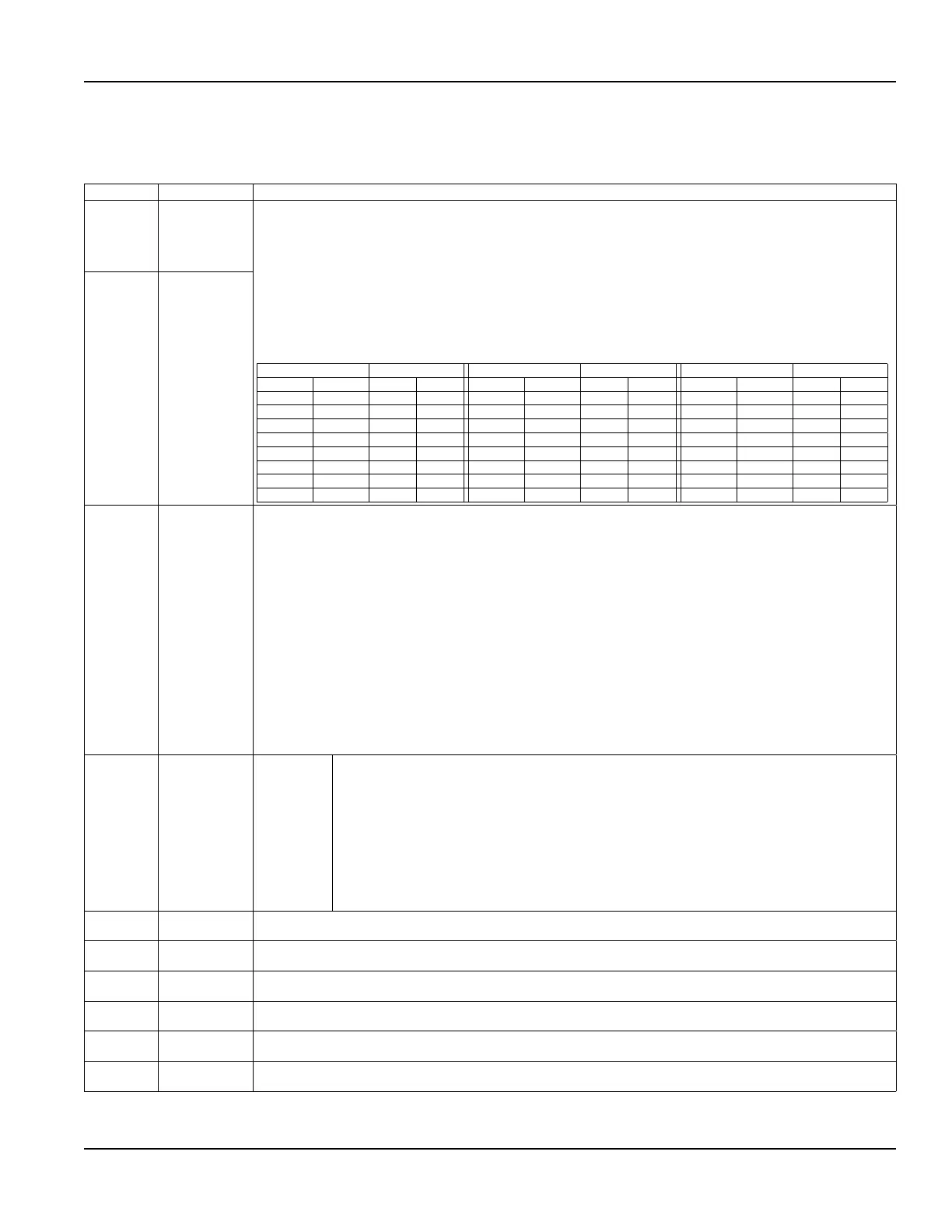
The following table lists sound speed values for water at varying temperatures. If the transmitter is measuring sound speed
within 2% of the table values, then the installation and setup of the instrument is correct.
Temperature Velocity Temperature Velocity Temperature Velocity
° C ° F mps fps ° C ° F mps fps ° C ° F mps fps
0 32 1402 4600 80 176 1554 5098 160 320 1440 4724
10 50 1447 4747 90 194 1550 5085 170 338 1412 4633
20 68 1482 4862 100 212 1543 5062 180 356 1390 4560
30 86 1509 4951 110 230 1532 5026 190 374 1360 4462
40 104 1529 5016 120 248 1519 4984 200 392 1333 4373
50 122 1543 5062 130 266 1503 4931 220 428 1268 4160
60 140 1551 5089 140 284 1485 4872 240 464 1192 3911
70 158 1555 5102 150 302 1466 4810 260 500 1110 3642
SSPD FPS
Liquid sound
speed in feet per
second
SIG STR
Signal strength
reported by the
firmware
The SIG STR value is a relative indication of the amount of ultrasound making it from the transmitting transducer to
the receiving transducer. The signal strength is a blending of esoteric transit time measurements distilled into a usable
overall reference.
The measurement of signal strength assists service personnel in troubleshooting the transmitter system. In general, expect
the signal strength readings to be greater than five on a full pipe with the transducers properly mounted. Signal strength
readings that are less than five indicate a need to choose an alternative mounting method for the transducers or that an
improper pipe size has been entered.
Signal strength below the low signal cutoff SIG C-OF value will generate a 0010 error (Low Signal Strength) and require
either a change in the SIG C-OF value or transducer mounting changes.
OTE:N If the transmitter is configured to display totalizer values, the display will alternate between error 0010 and the
totalizer value.
Signal strength readings in excess of 98 may indicate that a mounting method with a longer path length may be required.
For example, if transducers mounted on a 3 inch PVC pipe in V-Mount cause the measured signal strength value to exceed
98, change the mounting method to W-Mount for greater stability in readings.
Because signal strength is not an absolute indication of how well a transmitter is functioning, there is no real advantage to
a signal strength of 50 over a signal strength of 10.
SIG COF
Low signal cutoff
value
Options:
0.0…100.0
The SIG C-OF is used to drive the transmitter and its outputs to the SUB FLOW (Substitute Flow described
below) state if conditions occur that cause low signal strength. A signal strength indication below 5 is
generally inadequate for measuring flow reliably, so the minimum setting for SIG C-OF is 5. A good practice
is to set the SIG C-OF at approximately 60…70% of actual measured maximum signal strength.
OTE:N The factory default Signal Strength Cutoff is 5.
If the measured signal strength is lower than the SIG C-OF setting, an error 0010 will be shown on the
transmitter’s display until the measured signal strength becomes greater than the cutoff value.
A signal strength indication below 2 is considered to be no signal at all. Verify that the pipe is full of liquid,
the pipe size and liquid parameters are entered correctly, and that the transducers have been mounted
accurately. Highly aerated liquids will also cause low signal strength conditions.
TEMP 1 C
Temperature of
RTD 1
Reported by the firmware in C°. When RTD is selected from the CH2 menu and RTDs are connected to the Energy model,
the firmware will display the temperature measured by RTD 1 in ° C.
TEMP 1 F
Temperature of
RTD 1
Reported by the firmware in F°. When RTD is selected from the CH2 menu and RTDs are connected to the Energy model, the
firmware will display the temperature measured by RTD 1 in ° F.
TEMP 2 C
Temperature of
RTD 2
Reported by the firmware in C°. When RTD is selected from the CH2 menu and RTDs are connected to the Energy model,
the firmware will display the temperature measured by RTD 2 in ° C.
TEMP 2 F
Temperature of
RTD 2
Reported by the firmware in F°. When RTD is selected from the CH2 menu and RTDs are connected to the Energy model, the
firmware will display the temperature measured by RTD 2 in ° F.
TEMP DIFF C
Temperature
difference
Reported by the firmware in C°. When RTD is selected from the CH2 menu and RTDs are connected to the Energy model,
the firmware will display the difference in temperature measured between RTD 1 and RTD 2 in ° C.
TEMP DIFF F
Temperature
difference
Reported by the firmware in F°. When RTD is selected from the CH2 menu and RTDs are connected to the Energy model, the
firmware will display the difference in temperature measured between RTD 1 and RTD 2 in ° F.
Conguration
Page 45 May 2016 TTM-UM-00136-EN-06

 Loading...