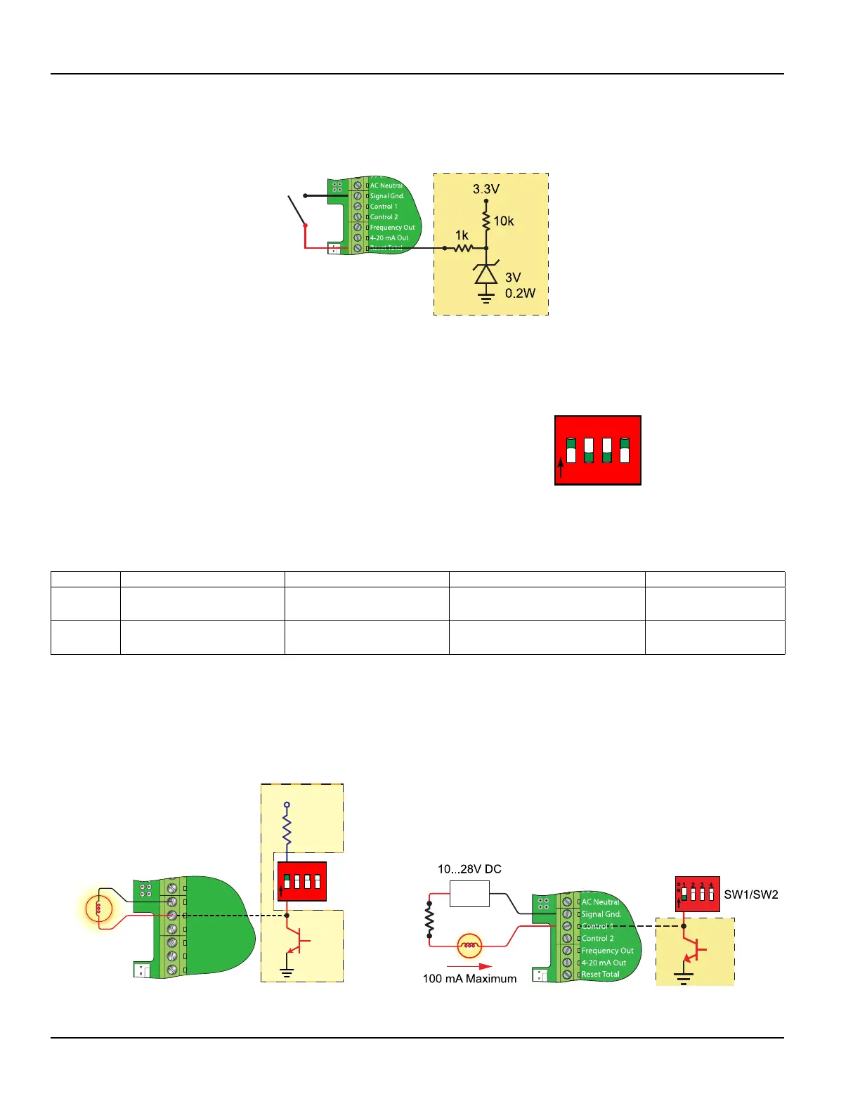
Reset Total Input
The Reset Total Input can be used with a push-button to reset the flow totals. When the Reset Total Input is connected to
signal ground, the total displayed on the meter is reset to zero.
Figure 25: Reset total input
Control Outputs (Flow-Only Model)
Two independent open collector transistor outputs are included with the Flow-Only model. Each output can be configured
for one of the following functions:
• Rate Alarm
• Signal Strength Alarm
• Totalizing/Totalizing Pulse
• Errors
• None
1 2 3 4
O
N
Figure 26: Switch settings
Both control outputs are rated for a maximum of 100 mA and 10…28V DC. A pullup resistor can be added externally or an
internal 10k Ohm pullup resistor can be selected using DIP switches on the power supply board.
Switch S1 S2 S3 S4
On
Control 1 Pullup
Resistor IN circuit
Control 2 Pullup
Resistor IN circuit
Frequency output Pullup Resistor
IN circuit
Square Wave Output
Off
Control 1 Pullup
Resistor OUT of circuit
Control 2 Pullup
Resistor OUT of circuit
Frequency Output Pullup Resistor
OUT of circuit
Simulated Turbine
Output
Table 5: Dip switch functions
OTE:N All control outputs are disabled when a USB cable is connected.
For the Rate Alarm and Signal Strength Alarm the on/off values are set using either the keypad or the UltraLink
software utility.
Typical control connections are illustrated in Figure 28. Please note that only the Control 1 output is shown. Control 2 is
identical except the pullup resistor is governed by SW2.
SW1/SW2
90-265 VAC
AC Neutral
Signal Gnd.
Control 2
Frequency Out
4-20 mA Out
Reset Total
10k
VCC
1 2 3 4
O
N
Control 1
Figure 27: Typical control connections
Inputs/Outputs
Page 26 May 2016TTM-UM-00136-EN-06

 Loading...