Bad Data Rejection is a value related to the number of successive readings that must be measured outside of the Flow Filter
Hysteresis or Flow Filter MinHysteresis windows before the transmitter will use that flow value. Larger values are entered into
Bad Data Rejection when measuring liquids that contain gas bubbles, as the gas bubbles tend to disturb the ultrasonic signals
and cause more extraneous flow readings to occur. Larger Bad Data Rejection values tend to make the transmitter more
sluggish to rapid changes in actual flow rate.
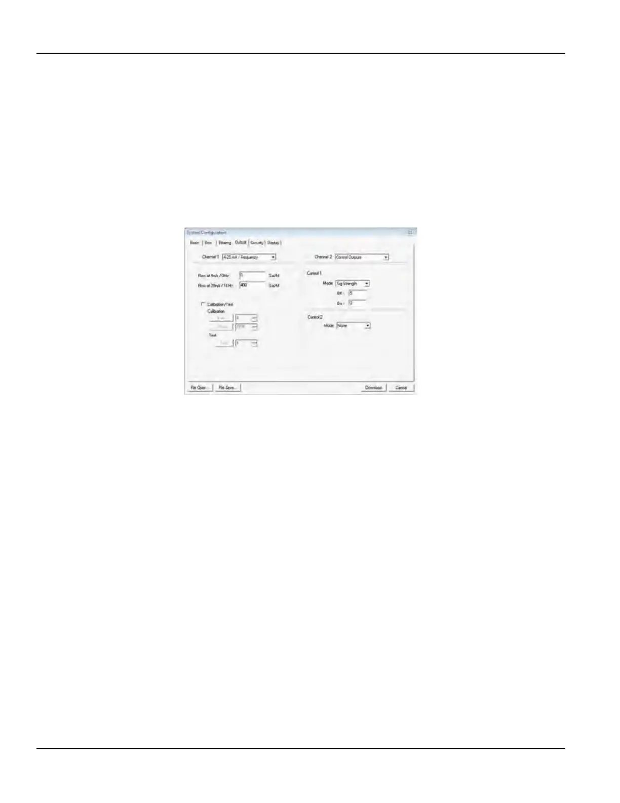
Output Tab
The entries made in the Output tab establish input and output parameters for the transmitter. Select the appropriate function
from the pull-down menu and click Download. When a function is changed from the factory setting, a configuration error
1002 will result. This error will be cleared by resetting the transmitter microprocessor from the Communications/Commands/
Reset Target button or by cycling power on the transmitter. Once the proper output is selected and the microprocessor is
reset, calibration and configuration of the modules can be completed.
Figure 45: Output tab
Channel 1, 4-20 mA Configuration
OTE:N The 4-20 mA Output menu applies to all transmitters and is the only output choice for Channel 1.
The channel 1 menu controls how the 4-20 mA output is spanned for all models and how the frequency output is spanned for
the flow-only model.
The Flow at 4 mA / 0 Hz and Flow at 20 mA / 1000 Hz settings are used to set the span for both the 4-20 mA output and the
0…1000 Hz frequency output on the Flow-Only model.
The 4-20 mA output is internally powered (current sourcing) and can span negative to positive flow/energy rates. This output
interfaces with virtually all recording and logging systems by transmitting an analog current that is proportional to system
flow rate. Independent 4 mA and 20 mA span settings are established in firmware using the flow measuring range entries.
These entries can be set anywhere in the –40…40 fps (–12 …12 mps) range of the instrument. Resolution of the output is
12 bits (4096 discrete points) and can drive up to a 400 Ohm load when the transmitter is AC powered. When powered by a
DC supply, the load is limited by the input voltage supplied to the instrument. See Figure 24 for allowable loop loads.
Flow at 4 mA / 0 Hz
Flow at 20 mA / 1000 Hz
The Flow at 4 mA / 0 Hz and Flow at 20 mA / 1000 Hz entries are used to set the span of the 4-20 mA analog output and
the frequency output on Flow-Only model. These entries are volumetric rate units that are equal to the volumetric units
configured as rate units and rate interval.
For example, to span the 4-20 mA output from –100…100 gpm with 12 mA being 0 gpm, set the Flow at 4 mA / 0 Hz and Flow
at 20 mA / 1000 Hz inputs as follows:
Flow at 4 mA / 0 Hz = –100.0
Flow at 20 mA / 1000 Hz = 100.0
Conguration Menu
Page 54 May 2016TTM-UM-00136-EN-06

 Loading...