Power Connections
Electrical Symbols
Function Direct Current Alternating Current Earth (Ground) Protective Ground Chassis Ground
Symbol
Table 1: Electrical symbols
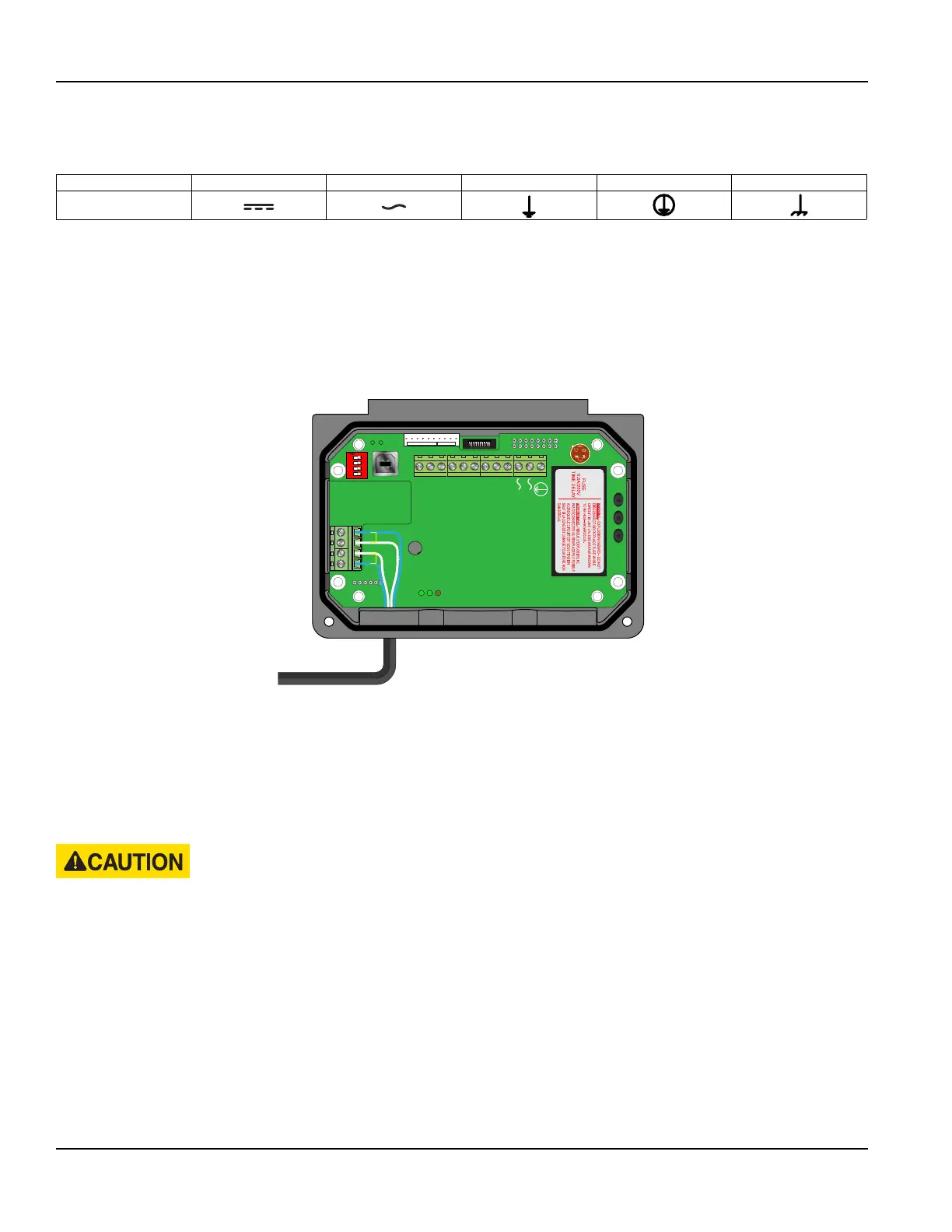
Transducer Connections
1. To access terminal strips for wiring, loosen the two screws in the enclosure door and open.
2. Guide the transducer terminations through the transmitter conduit hole in the bottom-left of the enclosure.
3. Secure the transducer cable with the supplied conduit nut (if exible conduit was ordered with the transducer).
4. The terminals within transmitter are screw-down barrier terminals. Connect the wires at the corresponding screw
terminals in the transmitter. Observe upstream and downstream orientation and wire polarity. See Figure 4.
Downstream
Upstream
+
+
-
-
Modbus
TFX Rx
TFX Tx
Signal Gnd.
Control 1
Control 2
Frequency Out
4-20 mA Out
Reset Total
RS485 Gnd
RS485 A(-)
RS485 B(+)
95 - 264 VAC
AC Neutral
W
R
C US
1500mA250V
D
VE
372
R
C US
E167432
$
TUV
PRODUCT SERVICE
RoHS
AC IN : 100-240VAC,50/60Hz
DC OUT :
+15V / 0.3A
PWC-15E
0.15A
R2807
www.astrodyne.com
-Vo
+Vo
ACL
ACN
strodyne
1 2 3 4
O
N
To Transducers
Downstream
Upstream
+
+
-
-
Figure 3: Transducer connections
OTE:N Transducer cables have two wire color combinations. For the blue and white combination, the blue wire is positive
(+) and the white wire is negative (–). For the red and black combination, the red wire is positive (+) and the black
wire is negative (–). The transducer wires are labeled to indicate which pair is upstream or downstream.
5. Connect power to the screw terminal block in the transmitter using the conduit hole on the right side of the enclosure.
See Figure 5 and Figure 6. Use wiring practices that conform to local and national codes such as The National Electrical
Code Handbook in the U.S.
ANY OTHER WIRING METHOD MAY BE UNSAFE OR CAUSE IMPROPER OPERATION OF THE TRANSMITTER.
OTE:N This transmitter requires clean electrical line power. Do not operate this transmitter on circuits with noisy
components (such as fluorescent lights, relays, compressors, or variable frequency drives). Do not use step-down
transformers from high voltage, high amperage sources. Do not to run signal wires with line power within the same
wiring tray or conduit.
Transmitter Installation
Page 12 May 2016TTM-UM-00136-EN-06
 Loading...
