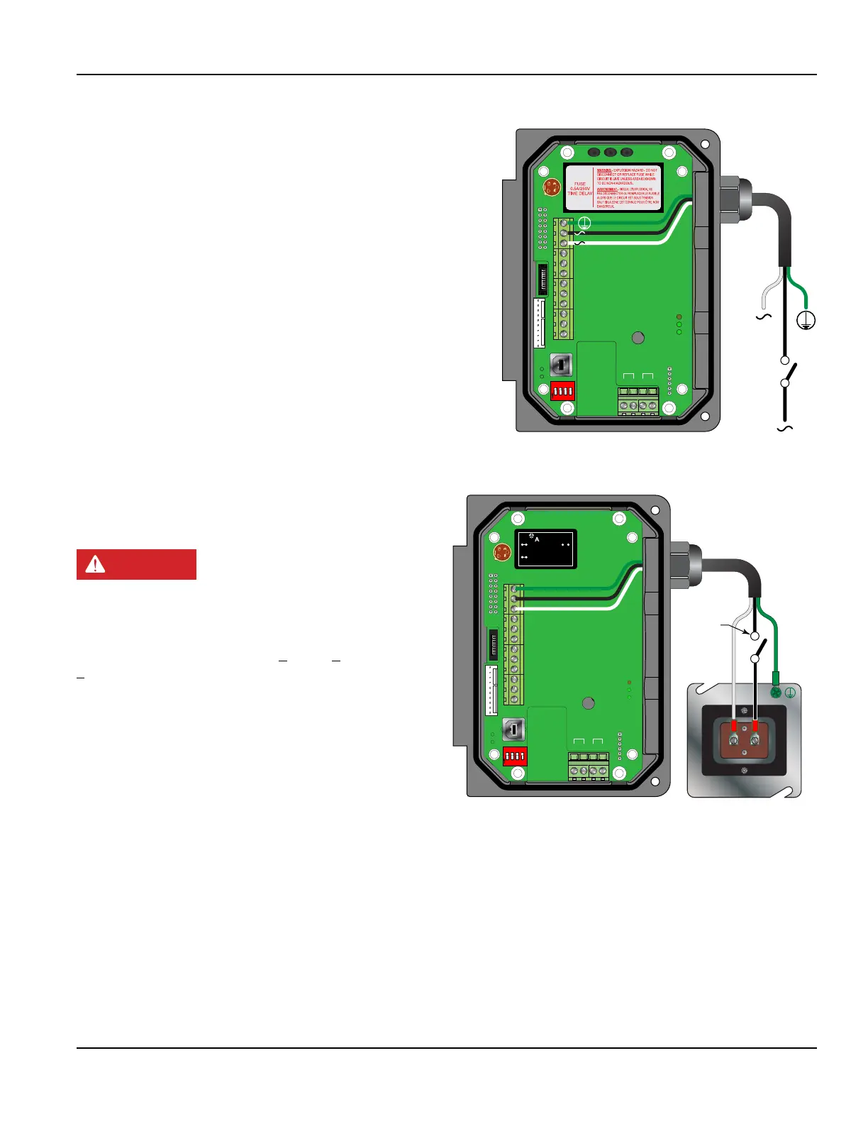
Line Voltage AC Power Connections
Connect 95…264V AC, AC neutral and chassis ground to the
terminals shown in Figure 5. Do not operate without an earth (chassis)
ground connection.
MPORTANTI
Permanently connected equipment and multi-phase equipment uses a
switch or circuit breaker as a means of disconnect. The switch or circuit
breaker conforms to the following:
• A switch or circuit breaker is included in the building installation.
• The switch is in close proximity to the equipment and within easy reach
of the operator.
• The switch is marked as the disconnecting device for the equipment.
Wiring of this equipment in ordinary locations must be in accordance with
ANSI/NFPA 70, National Electrical Code (NEC), Canadian Electrical Code
(CEC) or IEC 60364 as required by local codes. Wiring of this equipment in
hazardous locations requires special considerations such a those described
in National Electrical Code (NEC) Article 500, Canadian Electrical Code
(CEC), CSA C22.1 or IEC 60079-14.
Downstream
Upstream
+
+
-
-
Modbus
TFX Rx
TFX Tx
Signal Gnd.
Control 1
Control 2
Frequency Out
4-20 mA Out
Reset Total
RS485 Gnd
RS485 A(-)
RS485 B(+)
95 - 264 VAC
AC Neutral
W
R
C US
1500mA250V
D
VE
372
R
C US
E167432
$
TUV
PRODUCT SERVICE
RoHS
AC IN : 100-240VAC,50/60Hz
DC OUT :
+15V / 0.3A
PWC-15E
0.15A
R2807
www.astrodyne.com
-Vo
+Vo
ACL
ACN
strodyne
1 2 3 4
O
N
95 - 264 VAC
AC Neutral
Switch
or
Circuit
Breaker
Figure 4: Line voltage AC power connections
Low Voltage AC Power Connections
Connect 20…28V AC, AC neutral and chassis ground to the
terminals shown in Figure 6.
DANGER
DO NOT OPERATE WITHOUT AN EARTH CHASSIS
GROUND CONNECTION.
The 24V AC power supply option for this transmitter
is intended for a typical HVAC and Building Control
Systems (BCS) powered by a 24V AC, nominal, power
source. This power source is provided by AC line power
to 24V AC drop-down transformer and is installed by the
installation electricians.
OTE:N In electrically noisy applications, grounding the
transmitter to the pipe where the transducers are
mounted may provide additional noise suppression.
This approach is only effective with conductive metal
pipes. The earth (chassis) ground derived from the
line voltage power supply should be removed at
the transmitter and a new earth ground connected
between the transmitter and the pipe
being measured.
Downstream
Upstream
+
+
-
-
Modbus
TFX Rx
TFX Tx
Signal Gnd.
Control 1
Control 2
Frequency Out
4-20 mA Out
Reset Total
RS485 Gnd
RS485 A(-)
RS485 B(+)
W
R
C US
1500mA250V
D
VE
372
1 2 3 4
O
N
strodyne
-IN+
OUT+
OUT−
IN: 18-36VAC
OUT: 15VDC
ASD06-24S15
Test
P1
Chassis Gnd.
24 VAC
AC Neutral
Switch
or
Circuit
Breaker
Figure 5: Low voltage AC power connections
OTE:N Wire gauges up to 14 AWG can be accommodated in the transmitter terminal blocks.
OTE:N AC-powered transmitters are protected by a field-replaceable fuse. The fuse is a time delay fuse rated at 0.5A/250V
and is equivalent to Wickmann P.N. 3720500041 or 37405000410.
Transmitter Installation
Page 13 May 2016 TTM-UM-00136-EN-06

 Loading...