Transducer Mounting Congurations
V-Mount and W-Mount Configurations
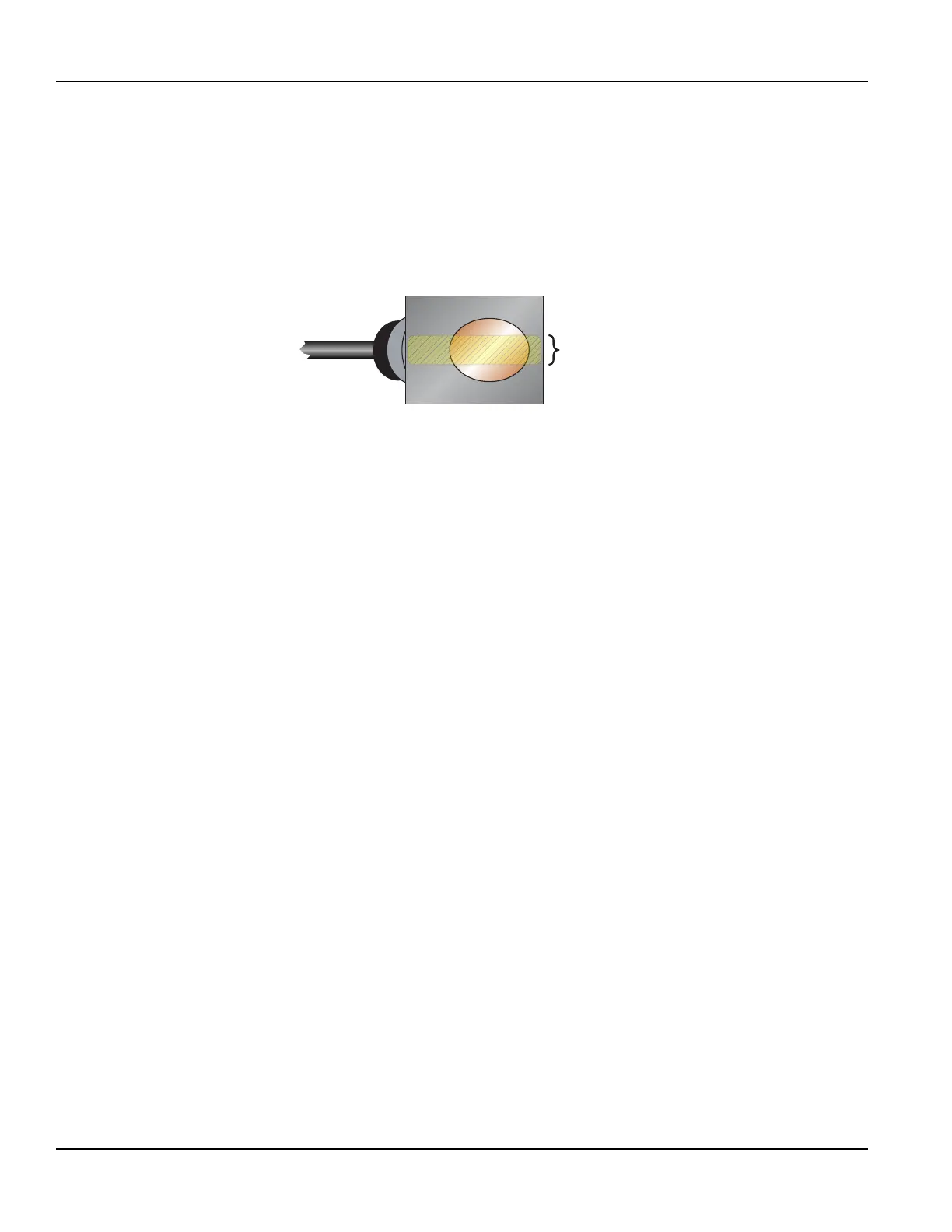
Apply the Couplant
For DTTR, DTTN, DTTL and DTTH transducers, place a single bead of couplant, approximately 1/2 inch (12 mm) thick, on the
flat face of the transducer. See Figure 12. Couplant is provided with the transducers. Generally, a silicone-based grease is used
as an acoustic couplant, but any good quality grease-like substance that is rated to not ow at the operating temperature
of the pipe is acceptable. For pipe surface temperature over 130° F (55° C), use high temperature acoustic coupant such as
Krytox® LVP (P.N. D002-2011-012). For installations that must be silicone free, use Molykote G-N couplant (P.N. D002-2011-009).
½ in.
(12 mm)
Figure 11: Application of couplant
Position and Secure the Transducer
1. Place the upstream transducer in position on the pipe. Slide the strap into the arched groove on the end of the transducer.
Wrap the strap around the pipe. Slide the free end of the strap into the end clip of the strap with the screw at 90 degrees
to the strap. Pull the strap through until it loosely ts around the pipe. Rotate the screw so it is parallel to the strap and
tighten the screw slightly to help hold the transducer onto the pipe. Verify that the transducer is true to the pipe and
adjust as necessary. Tighten the strap screw to secure the transducer to the pipe.
2. Place the downstream transducer on the pipe at the calculated transducer spacing. See Figure 13 on page21. Apply rm
hand pressure. If signal strength is greater than ve, secure the transducer at this location. If the signal strength is not ve
or greater, using rm hand pressure slowly move the transducer both towards and away from the upstream transducer
while observing signal strength.
Signal strength can be displayed on the transmitter’s display or on the main data screen in the UltraLink software utility.
See “Parameter Configuration Using UltraLink Software” on page48. Clamp the transducer at the position where the
highest signal strength is observed. The factory default signal strength setting is ve. However, there are many application-
specic conditions that may prevent the signal strength from attaining this level. Signal levels less than ve will probably
not be acceptable for reliable readings.
OTE:N Signal strength readings update only every few second. Move the transducer 1/8 inch then wait to see if the signal is
increasing or decreasing. Repeat until the highest level is achieved.
3. If, after adjusting the transducers, the signal strength does not rise to above ve, use an alternate transducer mounting
conguration. If the mounting conguration was W-Mount, re-congure the transmitter for V-Mount, move the
downstream transducer to the new spacing distance and repeat the procedure “Mount the Transducer” on page19.
Transducer Installation
Page 20 May 2016TTM-UM-00136-EN-06

 Loading...