TRANSDUCER INSTALLATION
The transducers for the TFX Ultra transmitter contain piezoelectric crystals that transmit and receive ultrasonic signals through
the walls of liquid piping systems.
DTTR, DTTN, DTTL and DTTH transducers are relatively simple and straightforward to install, but spacing and alignment of the
transducers is critical to the system’s accuracy and performance. CAREFULLY EXECUTE THESE INSTRUCTIONS.
DTTS and DTTC small pipe transducers have integrated transmitter and receiver elements that eliminate the requirement for
spacing measurement and alignment.
Mounting the DTTR, DTTN, DTTL and DTTH clamp-on ultrasonic transit time transducers takes five steps:
1. Select the optimum location on a piping system.
2. Select a mounting conguration.
3. Enter the pipe and liquid parameters into the UltraLink software utility or key them into the transmitter. The UltraLink
software utility or the transmitter’s rmware calculates proper transducer spacing based on these entries.
4. Prepare the pipe and mount the transducers.
5. Wire the transducers to the transmitter.
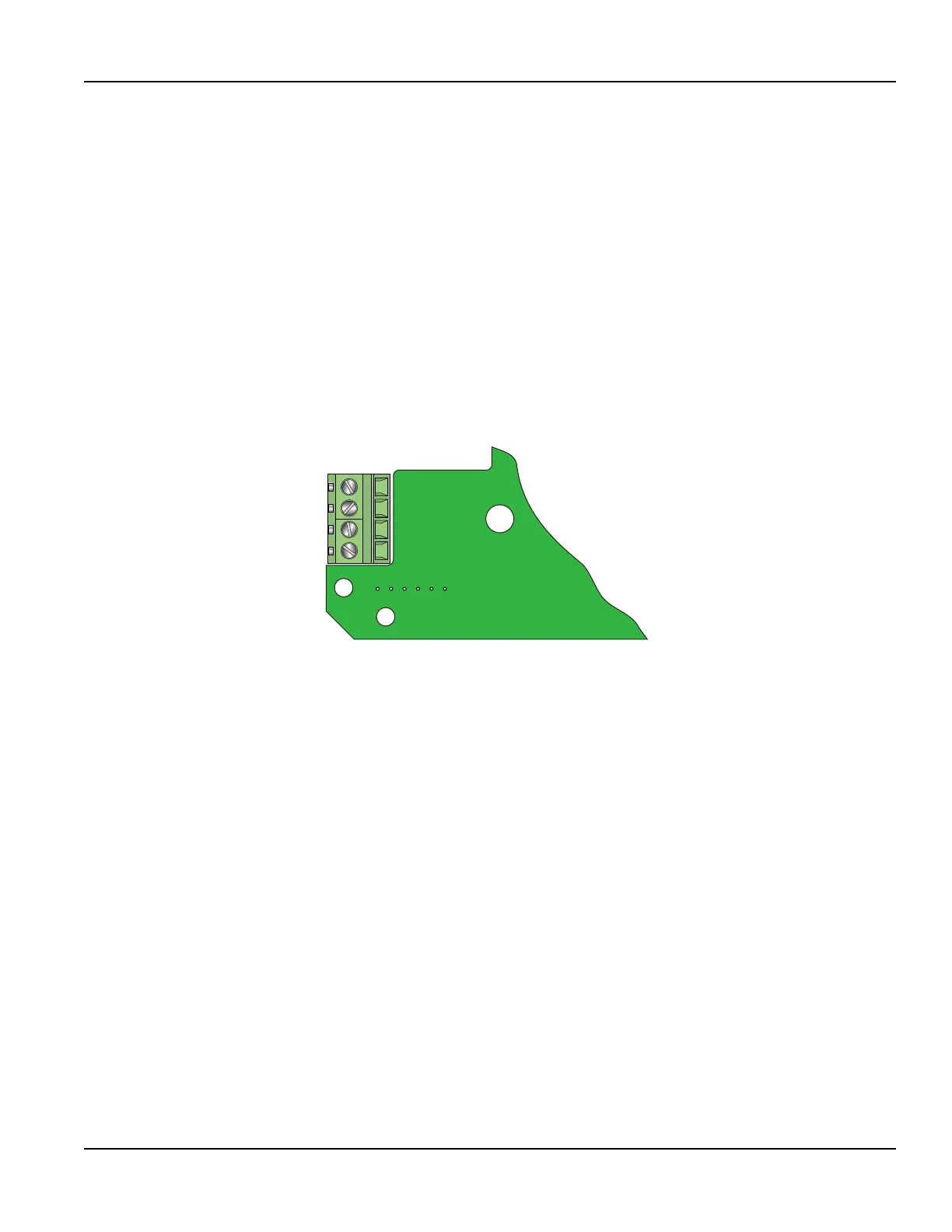
Downstream+
Downstream-
Upstream-
Upstream+
Figure 7: Transducer connections
The Energy model transmitter requires two 1000 Ohm, three-wire, platinum RTDs. The RTDs are available in surface-mount
and insertion (wetted) styles. Use surface-mount RTDs on well insulated pipes. Use insertion RTDs on non-insulated pipes.
Select a Mounting Location
The first step in the installation process is the selection of an optimum location for the flow measurement to be made. For this
to be done effectively, a basic knowledge of the piping system and its plumbing are required.
An optimum location is defined as:
• A piping system that is completely full of liquid when measurements are being taken. The pipe may become completely
empty during a process cycle, which will result in the error code 0010 (Low Signal Strength) displaying on the transmitter
while the pipe is empty. This error code will clear automatically once the pipe refills with liquid. Do not mount the
transducers in an area where the pipe may become partially filled, such as the highest point in a flow loop. Partially filled
pipes will cause erroneous and unpredictable operation of the transmitter.
• A piping system that contains lengths of straight pipe such as those described in Table 1. The optimum straight pipe
diameter recommendations apply to pipes in both horizontal and vertical orientation. The straight runs in Table 1 apply to
liquid velocities that are nominally 7 fps (2.2 mps). As liquid velocity increases above this nominal rate, the requirement for
straight pipe increases proportionally.
• An area where the transducers will not be inadvertently bumped or disturbed during normal operation.
• NOT on downward flowing pipes unless adequate downstream head pressure is present to overcome partial filling of or
cavitation in the pipe.
Transducer Installation
Page 15 May 2016 TTM-UM-00136-EN-06

 Loading...