Service Menu (SER) continued
Parameter Meaning Options Description
SUB FLOW
Substitute flow
value
0.0…100.0
Substitute Flow SUB FLOW is a value that the analog outputs and the flow rate display will indicate when
an error condition in the transmitter occurs. The typical setting for this entry is a value that will make the
instrument display zero flow during an error condition.
Substitute flow is set as a percentage between MIN RATE and MAX RATE. In a unidirectional system, this
value is typically set to zero to indicate zero flow while in an error condition. In a bidirectional system,
the percentage can be set such that zero is displayed in a error condition. To calculate where to set the
substitute flow value in a bidirectional system, perform the following calculation:
100
100 -
-
×
=
Maximum F low
S ubstitute F low
Maximum F low Minimum F low
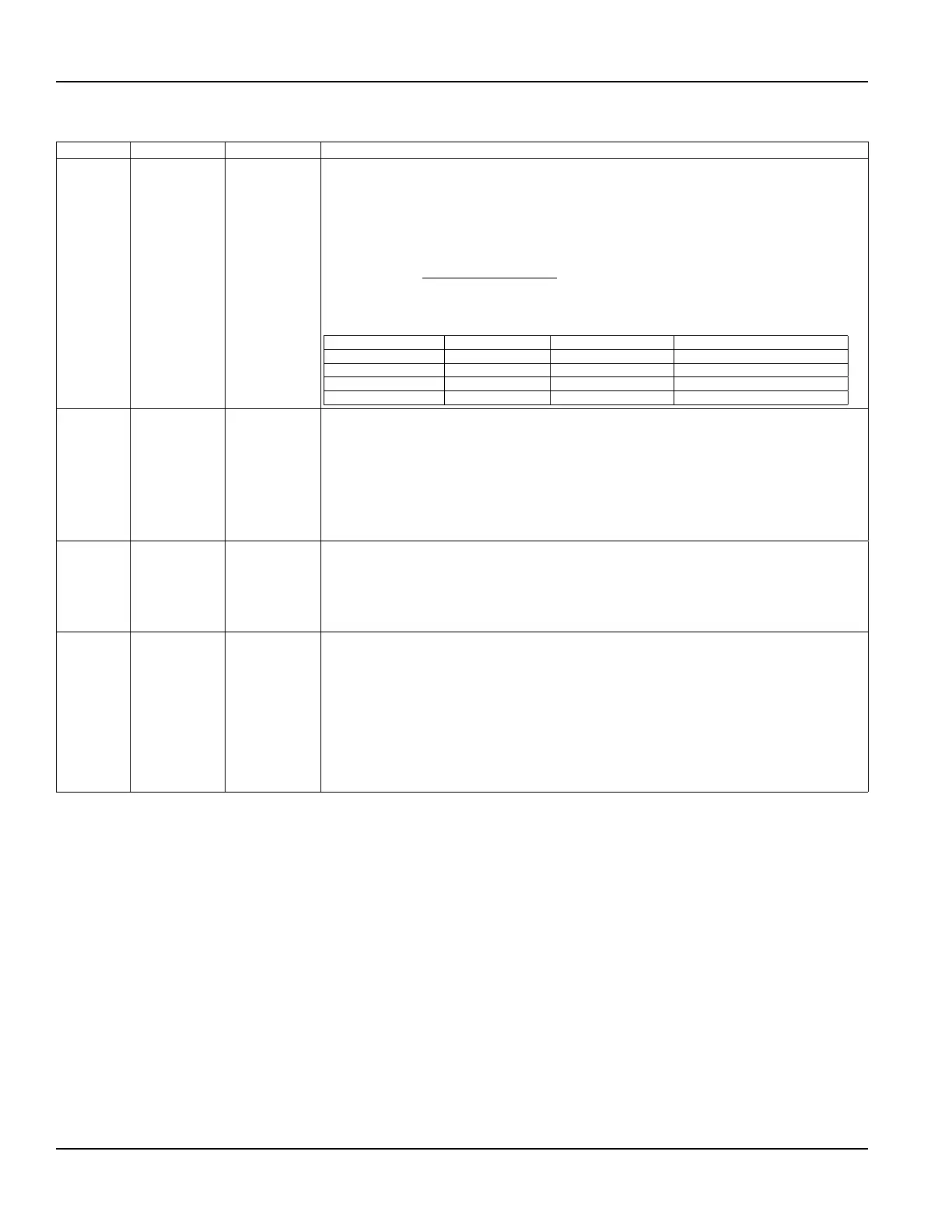
Some typical settings to achieve zero with respect to MIN RATE and MAX RATE settings are listed below.
OTE:N *The UltraLink software utility is required to set values outside of 0.0…100.0.
Min Rate Setting Max Rate Setting Sub Flow Setting Display Reading During Errors
0.0 1000.0 0.0 0.000
-500.0 500.0 50.0 0.000
-100.0 200.0 33.3 0.000
0.0 1000.0 -5.0* -50.00
SET ZERO
Set zero flow
point
NO
YES
Because every transmitter installation is slightly different and sound waves can travel in slightly
different ways through these various installations, it is important to remove the zero offset at zero flow
to maintain the transmitter’s accuracy. A provision is made using this entry to establish “Zero” flow and
eliminate the offset.
1. The pipe must be full of liquid.
2. Flow must be absolute zero - securely close any valves and allow time for any settling to occur.
3. Press ENTER, use the arrow keys to make the display read YES.
4. Press ENTER.
DFLT 0
Set default zero
point
NO
YES
If the flow in a piping system cannot be shut off, allowing the SET ZERO procedure described above to
be performed or if an erroneous “zero” flow was captured - like can happen if SET ZERO is conducted
with flowing fluid, then the factory default zero should be used. To use the D-FLT 0 function, simply
press ENTER, then press an arrow key to display YES on the display and then press ENTER.
The default zero places an entry of zero (0) into the firmware instead of the actual zero offset entered by
using the SET ZERO procedure.
COR FTR
Correction
Factor
0.500…1.500
This function can be used to make the transmitter agree with a different (or reference) transmitter by
applying a correction factor / multiplier to the readings and outputs. A factory calibrated system should
be set to 1.000. The range of settings for this entry is 0.500 to 1.500. The following examples describe two
uses for the COR FTR entry:
• The transmitter is indicating a flow rate that is 4% higher than another transmitter located in the
same pipe line. To make the transmitter indicate the same flow rate as the other transmitter, enter a
COR FTR of 0.960 to lower the readings by 4%.
• An out-of-round pipe, carrying water, causes the transmitter to indicate a measured sound speed
that is 7.4% lower than the Table 4.5 value. This pipe condition will cause the transmitter to indicate
flow rates that are 7.4% lower than actual flow. To correct the flow readings, enter 1.074.
Conguration
Page 46 May 2016TTM-UM-00136-EN-06

 Loading...