INPUTS/OUTPUTS
General
The transmitting system is available in two configurations:
• The Flow-Only model is equipped with a 4-20 mA output, two open collector outputs, a rate frequency output, and
RS485 communications using the Modbus RTU command set.
• The Energy (BTU) model has inputs for two 1000 Ohm RTD sensors in place of the rate frequency and alarm outputs. This
model allows the measurement of pipe input and output temperatures so energy usage calculations can be performed.
4-20 mA Output
The 4-20 mA output interfaces with most recording and logging systems by transmitting an analog current signal that is
proportional to system flow rate. The 4-20 mA output is internally powered (current sourcing) and can span negative to
positive flow/energy rates.
For AC-powered transmitters, the 4-20 mA output is driven from a 15V DC source located within the transmitter. The source
is isolated from earth ground connections within the transmitter. The AC-powered transmitter can accommodate loop loads
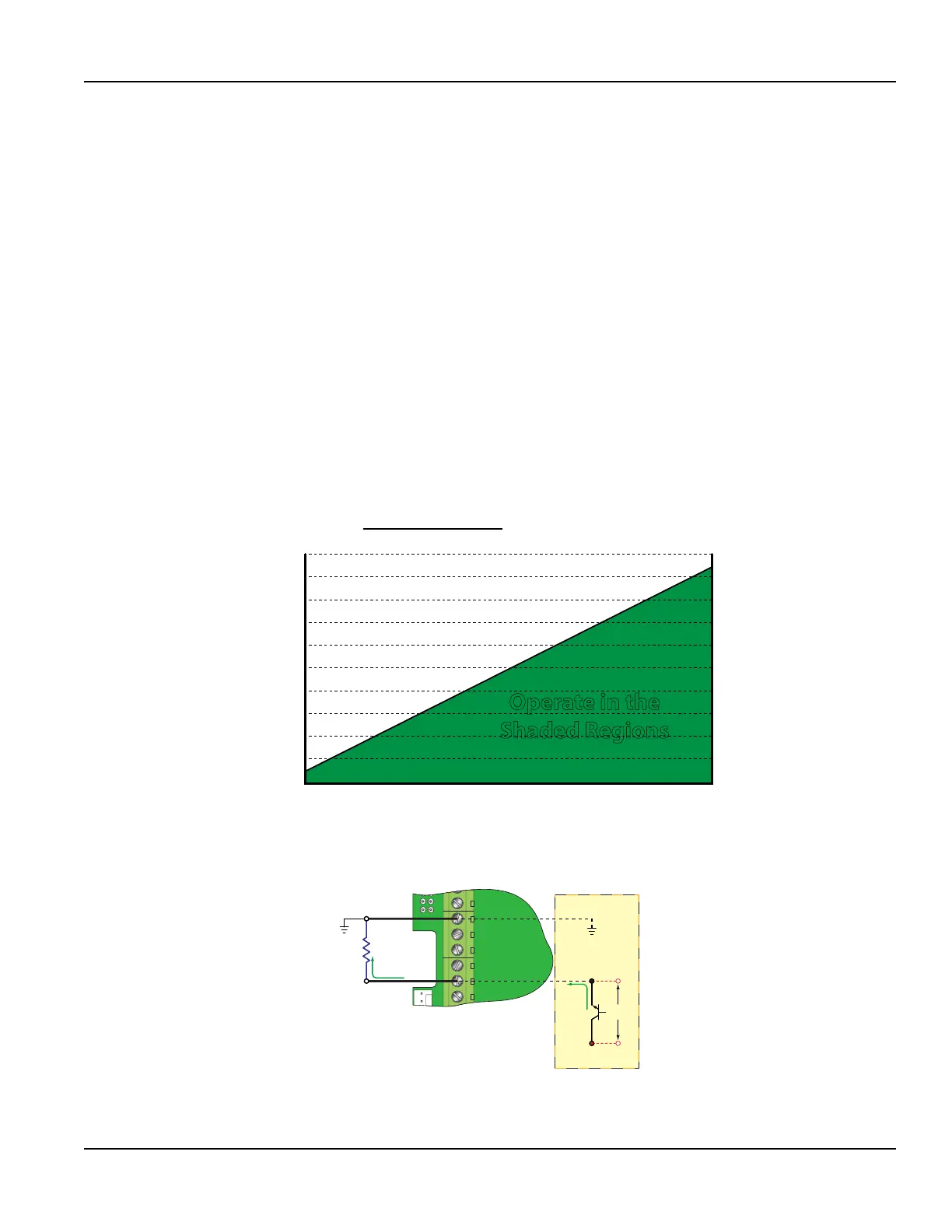
up to 400 Ohms. DC-powered transmitters use the DC power supply voltage to drive the current loop. The current loop
is not isolated from DC ground or power. Figure 24 shows graphically the allowable loads for various input voltages. The
combination of input voltage and loop load must stay within the shaded area of Figure 24.
200
100
300
400
500
600
700
800
900
1000
1100
10 12 14 16 18 20 22 24 26 28
Supply Voltage (VDC)
Operate in the
Shaded Regions
Supply Voltage - 7 VDC
0.02
= Maximum Loop Resistance
Figure 23: Allowable loop resistance (DC powered transmitters)
90-265 VAC
AC Neutral
Control 1
Control 2
Frequency Out
4-20 mA Out
Reset Total
Signal Gnd.
Meter Power
Loop
Resistance
Signal Ground
7 VDC
Drop
Figure 24: 4-20 mA output
The 4-20 mA output signal is available between the 4-20 mA Out and Signal Gnd terminals as shown in Figure 25.
Inputs/Outputs
Page 25 May 2016 TTM-UM-00136-EN-06
 Loading...
