Mounting Rail System Installation for DTTR
For remote flow DTTR transducers with outside diameters between 2…10 inches (50…250 mm) , the rail mounting kit aids
in installation and positioning of the transducers. Transducers slide on the rails, which have measurement markings that are
viewable through the sight opening.
1. Install the single mounting rail on the side of the pipe with the stainless steel bands provided. Do not mount it on the top
or bottom of the pipe. On vertical pipe, orientation is not critical. Check that the track is parallel to the pipe and that all
four mounting feet are touching the pipe.
2. Slide the two transducer clamp brackets toward the center mark on the mounting rail.
3. Place a single bead of couplant, approximately 1/2 inch (12 mm) thick, on the at face of the transducer.
See Figure 12 on page20.
4. Place the rst transducer in between the mounting rails near the zero point on the scale. Slide the clamp over the
transducer. Adjust the clamp and transducer so the notch in the clamp aligns with the zero on the scale. See Figure 23.
5. Secure with the thumb screw. Check that the screw rests in the counter bore on the top of the transducer. (Excessive
pressure is not required. Apply just enough pressure so that the couplant lls the gap between the pipe and transducer.)
6. Place the second transducer in between the mounting rails near the dimension derived in the transducer spacing section.
Read the dimension on the mounting rail scale. Slide the transducer clamp over the transducer and secure with the
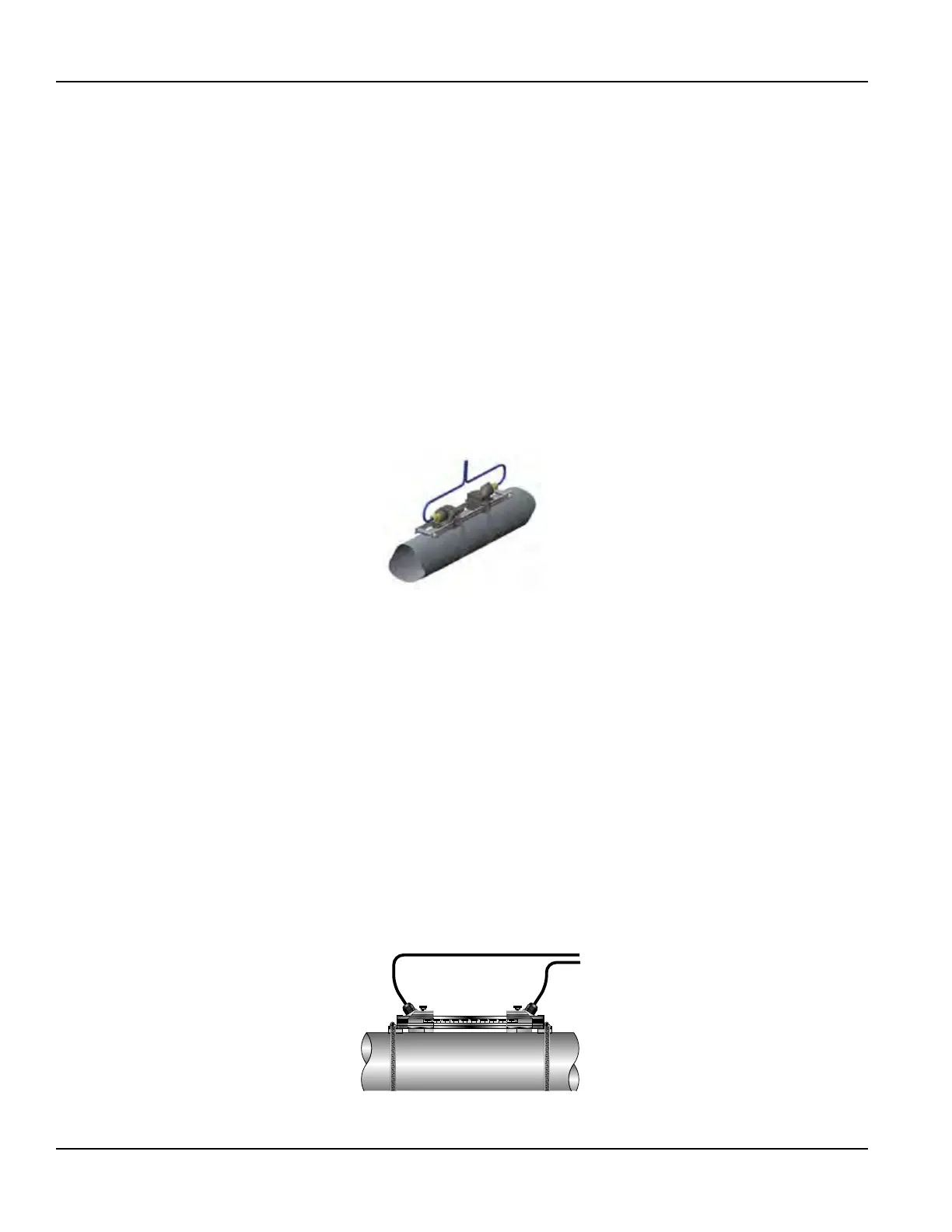
thumb screw.
Figure 21: Mounting rail system for DTTR
Mounting Track Installation for DTTN/DTTH
A convenient transducer mounting track can be used for pipes that have outside diameters between 2…10 inches
(50…250 mm) and for DTTN/DTTH transducers. If the pipe is outside of that range, mount the transducers separately.
1. Install the single mounting rail on the side of the pipe with the stainless steel bands provided. Do not mount it on the top
or bottom of the pipe. On vertical pipe, orientation is not critical. Check that the track is parallel to the pipe and that all
four mounting feet are touching the pipe.
2. Slide the two transducer clamp brackets toward the center mark on the mounting rail.
3. Place a single bead of couplant, approximately 1/2 inch (12 mm) thick, on the at face of the transducer.
See Figure 12 on page20.
4. Place the rst transducer in between the mounting rails near the zero point on the scale. Slide the clamp over the
transducer. Adjust the clamp and transducer so the notch in the clamp aligns with the zero on the scale. See Figure 23.
5. Secure with the thumb screw. Check that the screw rests in the counter bore on the top of the transducer. (Excessive
pressure is not required. Apply just enough pressure so that the couplant lls the gap between the pipe and transducer.)
6. Place the second transducer in between the mounting rails near the dimension derived in the transducer spacing section.
Read the dimension on the mounting rail scale. Slide the transducer clamp over the transducer and secure with the
thumb screw.
Top View
of Pipe
Figure 22: Mounting track installation
Transducer Installation
Page 24 May 2016TTM-UM-00136-EN-06

 Loading...