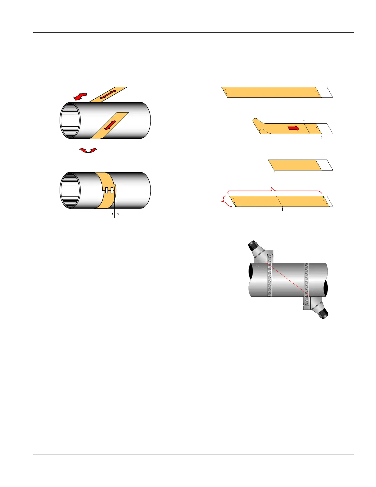
4. The two marks on the pipe are now properly aligned and measured. If access to the bottom of the pipe prohibits the
wrapping of the paper around the circumference, cut a piece of paper 1/2 the circumference of the pipe and lay it over the
top of the pipe. The equation for the length of 1/2 the circumference is: 1/2 Circumference = Pipe O.D. × 1.57
The transducer spacing is the same as found in “Position and Secure the Transducer” on page20. Mark opposite corners of the
paper on the pipe. Apply transducers to these two marks.
LESS THAN ¼” (6 mm)
Figure 18: Paper template alignment
Line Marking
Circumference
Edge of
Paper
Fold
Pipe Circumference
Crease
(Center of Pipe)
Transducer
Spacing
Figure 19: Bisecting the pipe circumference
5. For DTTR, DTTN, DTTL and DTTH transducers, place a single bead of
couplant, approximately 1/2 inch (12 mm) thick, on the at face of the
transducer. See Figure 12. Generally, a silicone-based grease is used
as an acoustic couplant, but any good quality grease-like substance
that is rated to not ow at the operating temperature of the pipe
is acceptable.
6. Place the upstream transducer in position and secure with a stainless
steel strap or other fastening device. Straps should be placed in the
arched groove on the end of the transducer. A screw is provided to help
hold the transducer onto the strap. Verify that the transducer is true to
the pipe, adjust as necessary. Tighten transducer strap securely. Larger
pipes may require more than one strap to reach the circumference of
the pipe.
TOP VIEW
OF PIPE
Figure 20: Z-Mount transducer placement
7. Place the downstream transducer on the pipe at the calculated transducer spacing. See Figure 21. Using rm hand
pressure, slowly move the transducer both towards and away from the upstream transducer while observing signal
strength. Clamp the transducer at the position where the highest signal strength is observed. A signal strength between
5…98 is acceptable.
The factory default signal strength setting is five. However there are many application-specific conditions that may
prevent the signal strength from attaining this level. A minimum signal strength of five is acceptable as long as this signal
level is maintained under all flow conditions.
On certain pipes, a slight twist to the transducer may cause signal strength to rise to acceptable levels. Certain pipe and
liquid characteristics may cause signal strength to rise to greater than 98. The problem with operating this transmitter with
very high signal strength is that the signals may saturate the input amplifiers and cause erratic readings. Strategies for
lowering signal strength would be changing the transducer mounting method to the next longest transmission path. For
example, if there is excessive signal strength and the transducers are mounted in a Z-Mount, try changing to V-Mount or
W-Mount. Finally, you can also move one transducer slightly off-line with the other transducer to lower signal strength.
8. Secure the transducer with a stainless steel strap or other fastener.
Transducer Installation
Page 23 May 2016 TTM-UM-00136-EN-06

 Loading...