DTTS/DTTC Small Pipe Transducer Calibration Procedure
1. Establish communications with the transit time transmitter.
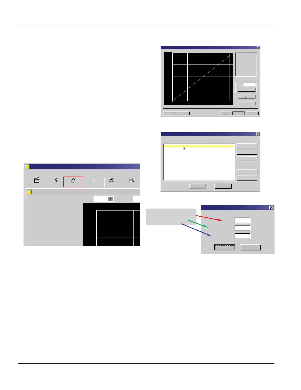
2. From the tool bar, select Calibration. See Figure 17.
3. On the pop-up screen, click Next twice to get to
Page 3 of 3. See Figure 15.
4. Click Edit.
5. If a calibration point is displayed in Calibration Points Editor,
record the information, then highlight and click Remove.
See Figure 16.
6. Click ADD...
7. Enter Delta T, Un-calibrated Flow, and Calibrated Flow
values from the DTTS/DTTC calibration label, then click OK.
See Figure 18.
8. Click OK in the Edit Calibration Points screen.
9. The display will return to Page 3 of 3. Click Finish.
See Figure 15.
10. After Writing Conguration File is complete, turn o the
power. Turn on the power again to activate the new
settings.
Calibration (Page 3 of 3) - Linearization
CancelFile Open... File Save...
< Back
Finish
Gal/M
Delta Time
1) Please establish a
reference flow rate.
1FPS / 0.3MPS Minimum.
2) Enter the reference flow
rate below. (Do not enter 0)
3) Wait for flow to stabilize.
4) Press the Set button.
Flow:
Set
Export...
Edit
28.2
Figure 14: Calibration points editor
Calibration Points Editor
Select point(s) to edit or remove:
Add...
Remove
Select All
Select All
Select None
Select None
Edit...
Cancel
OK
30.00 ns 2000.00 Gal/Min 1.000
Figure 15: Calibration page 3 of 3
UltraLINK Device Addr 127
Device Addr 127
Flow:
Totalizer Net:
Pos:
Neg:
Sig. Strength:
Margin:
Delta T:
Last Update:
HelpWindowCommunicationsViewEditFile
Print PreviePrint
1350 Gal/Min
0 OB
15.6%
100%
-2.50 ns
09:53:39
0 OB
0 OB
Errors
!
Configuration CalibrationStrategy
1600
2000
1200
Scale:60 MinTime:
200
U
U
Figure 16: Data display screen
Model: DTTSJP-050-N000-N
S/N: 39647 Delta-T: 391.53nS
Uncal. Flow: 81.682 GPM
Cal. Flow: 80 GPM
391.53
81.682
80.000
Delta T:
Uncalibrated Flow:
Calibrated Flow:
ns
Gal/Min.
Gal/Min.
Cancel
OK
Edit Calibration Points
Figure 17: Edit calibration points
Z-Mount Configuration
Installation on larger pipes requires careful measurements of the linear and radial placement of the DTTR, DTTN, DTTL and
DTTH transducers. Failure to properly orient and place the transducers on the pipe may lead to weak signal strength and/or
inaccurate readings. This section details a method for properly locating the transducers on larger pipes. This method requires
a roll of paper such as freezer paper or wrapping paper, masking tape and a marking device.
1. Wrap the paper around the pipe in the manner shown in Figure 19. Align the paper ends to within 1/4 inch (6 mm).
2. Mark the intersection of the two ends of the paper to indicate the circumference. Remove the template and spread it out
on a at surface. Fold the template in half, bisecting the circumference. See Figure 20.
3. Crease the paper at the fold line. Mark the crease. Place a mark on the pipe where one of the transducers will be located.
See Figure 10 for acceptable radial orientations. Wrap the template back around the pipe, placing the beginning of the
paper and one corner in the location of the mark. Move to the other side of the pipe and mark the pipe at the ends of
the crease. Measure from the end of the crease (directly across the pipe from the rst transducer location) the dimension
derived in “Select a Mounting Configuration” on page17. Mark this location on the pipe.
Transducer Installation
Page 22 May 2016TTM-UM-00136-EN-06

 Loading...