Frequency Output (Flow-Only Model)
The frequency output is an open-collector transistor circuit that outputs a pulse waveform that varies proportionally with flow
rate. This type of frequency output is also know as a Rate Pulse output. The output spans from 0 Hz, normally at zero flow rate
to 1000 Hz at full flow rate (configuration of the MAX RATE parameter is described in “Startup” on page35.
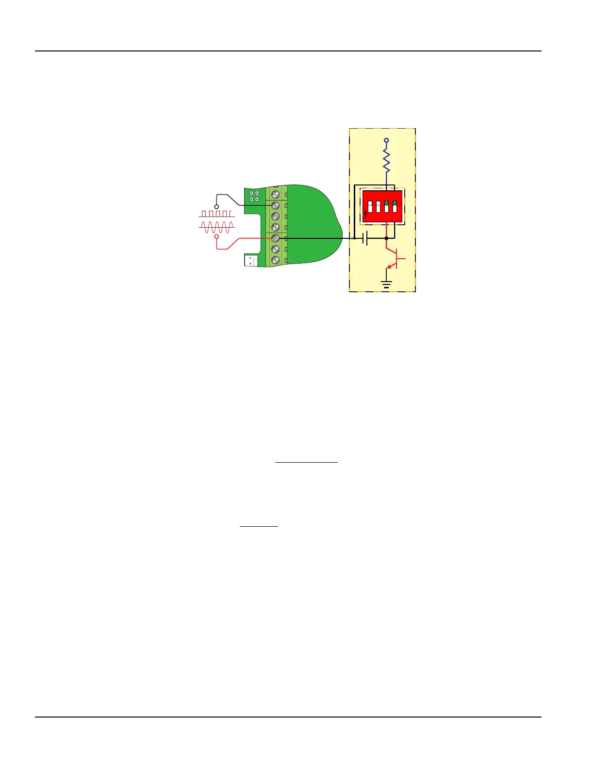
90-265 VAC
AC Neutral
Signal Gnd.
Control 2
Frequency Out
4-20 mA Out
Reset Total
10k
+V
1 2 3 4
O
N
Control 1
SW4 Closed
SW4 Open
Frequency Output
Figure 29: Frequency output switch settings
OTE:N When a USB programming cable is connected, the RS485 and frequency outputs are disabled.
The frequency output is proportional to the maximum flow rate entered into the transmitter. The maximum output frequency
is 1000 Hz.
If, for example, the MAX RATE parameter was set to 400 gpm, then an output frequency of 500 Hz (half of the full scale
frequency of 1000 Hz) would represent 200 gpm.
In addition to the control outputs, the frequency output can be used to provide total information by use of a Kfactor. A
Kfactor simply relates the number of pulses from the frequency output to the number of accumulated pulses that equates to
a specific volume.
For this transmitter, the relationship is described by the following equation. The 60,000 relates to measurement units in
volume/min. Measurement units in seconds, hours or days would require a different numerator.
60,000
K factor
Full Scale Units
=
A practical example would be if the MAX RATE for the application were 400 gpm, the Kfactor (representing the number of
pulses accumulated needed to equal one gallon) would be:
60,000
150
400
Pulses Per Gallon
gpm
K factor
= =
If the frequency output is to be used as a totalizing output, the transmitter and the receiving instrument must have identical
Kfactor values programmed into them to ensure that accurate readings are being recorded by the receiving instrument.
Unlike standard mechanical transmitters such as turbines, gear or nutating disc meters, the Kfactor can be changed by
modifying the MAX RATE flow rate value. See “Calculating KFactors” on page106.
Inputs/Outputs
Page 28 May 2016TTM-UM-00136-EN-06

 Loading...