Flow Tab
Flow Rate Units are selected from the drop-down lists. Select an appropriate rate unit and time from the two lists. This entry
also includes the selection of Flow Rate Interval after the virgule ( / ) sign.
Totalizer Units are selected from dropdown lists. Select an appropriate totalizer unit and totalizer exponent. The totalizer
exponents are in scientific notation and permit the eight digit totalizer to accumulate very large values before the totalizer
“rolls over” and starts again at zero.
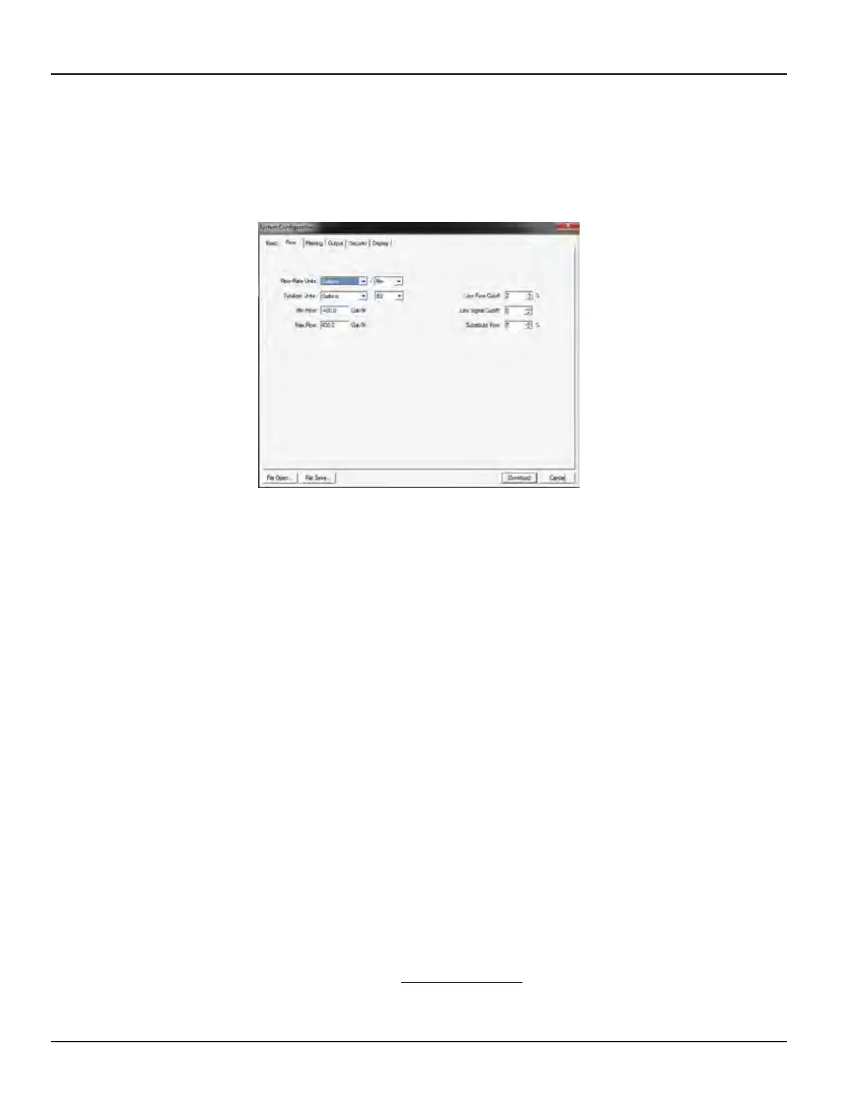
Figure 43: Flow tab
Min Flow is the minimum volumetric flow rate setting entered to establish filtering parameters. Volumetric entries will be in
the flow rate units. For unidirectional measurements, set Min Flow to zero. For bidirectional measurements, set Min Flow to the
highest negative (reverse) flow rate expected in the piping system.
Max Flow is the maximum volumetric flow rate setting entered to establish filtering parameters. Volumetric entries will be in
the flow rate units. For unidirectional measurements, set Max Flow to the highest (positive) flow rate expected in the piping
system. For bidirectional measurements, set Max Flow to the highest (positive) flow rate expected in the piping system.
Low Flow Cutoff is provided to allow very low flow rates (that can be present when pumps are off and valves are closed) to be
displayed as zero flow. Typical values that should be entered are between 1.0…5.0% of the flow range between
Min Flow and Max Flow.
Low Signal Cutoff is used to drive the transmitter and its outputs to the value specified in the Substitute Flow field when
conditions occur that cause low signal strength. A signal strength indication below 5 is generally inadequate for measuring
flow reliably, so generally the minimum setting for low signal cutoff is 5. A good practice is to set the low signal cutoff at
approximately 60…70% of actual measured maximum signal strength. The factory default low signal cutoff is five.
If the measured signal strength is lower than the low signal cutoff setting, a Signal Strength too Low highlighted in red will
become visible in the text area to the left in the Data Display screen until the measured signal strength becomes greater than
the cutoff value.
Signal strength indication below two is considered to be no signal at all. Verify that the pipe is full of liquid, the pipe size and
liquid parameters are entered correctly, and that the transducers have been mounted accurately. Highly aerated liquids will
also cause low signal strength conditions.
Substitute Flow is a value that the analog outputs and the flow rate display will indicate when an error condition in the
transmitter occurs. The typical setting for this entry is a value that will make the instrument display zero flow during an
error condition.
Substitute flow is set as a percentage between Min Flow and Max Flow. In a unidirectional system, this value is typically set
to zero to indicate zero flow while in an error condition. In a bidirectional system, the percentage can be set such that zero is
displayed in an error condition. To calculate where to set the Substitute Flow value in a bidirectional system, use:
100
100 -
-
×
=
Maximum F low
S ubstitute F low
Maximum F low Minimum F low
Conguration Menu
Page 52 May 2016TTM-UM-00136-EN-06

 Loading...