Basic Menu (BSC) continued
Parameter Meaning Options Description
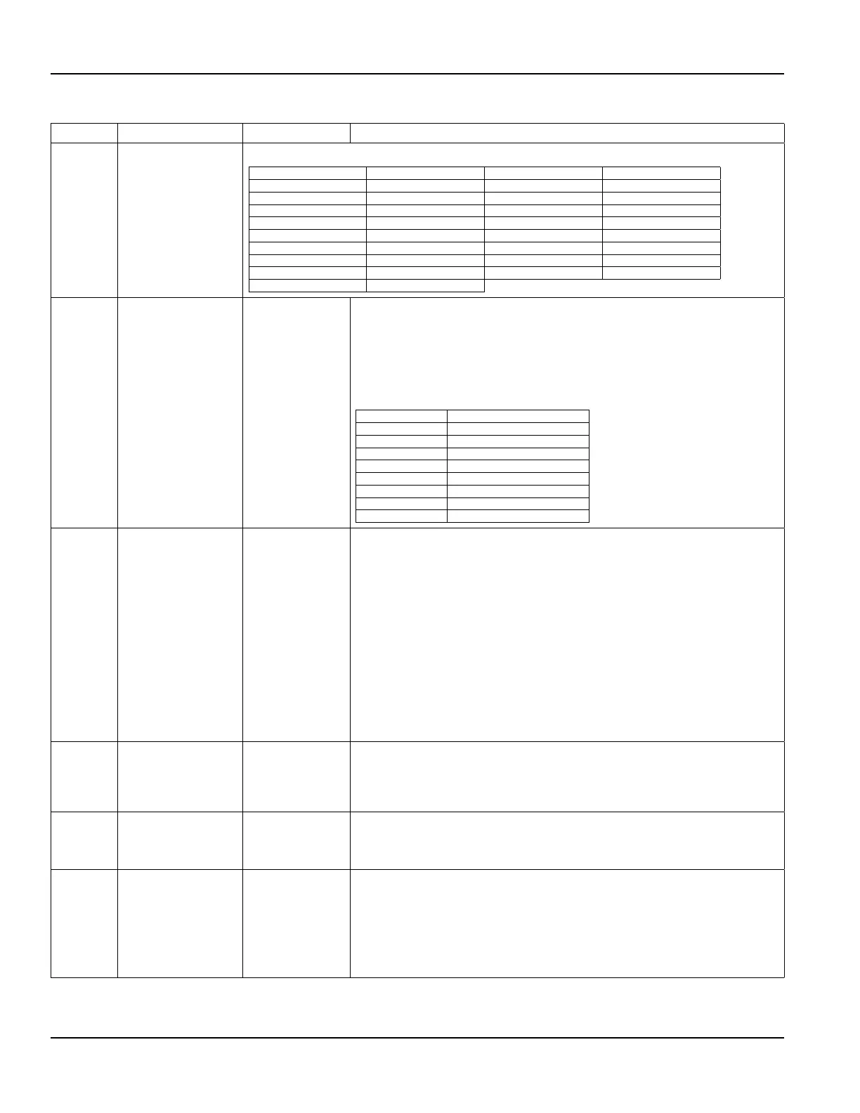
TOTL UNT Totalizer units
Select an engineering unit for flow totalizer measurements.
US Gallons US Gallons Pounds LB
Liters Liters Kilograms KG
Millions of US Gallons MGal British Thermal Units BTU
Cubic Feet Cubic Ft Thousands of BTUs MBTU
Cubic Meters Cubic Me Millions of BTUs MMBTU
Acre Feet Acre Ft 1 Ton/HR = 12000 BTU TONHR
Oil Barrels Oil Barr [42 US Gallons] Kilojoule kJ
Liquid Barrels Liq Barr [31.5 US Gallons] Kilowatt kWH
Feet Feet Megawatt MWH
Meters Meters
TOTL E
Flow totalizer exponent
value
E1…E6
Used for setting the flow totalizer exponent. This feature is useful for accommodating
a very large accumulated flow or to increase totalizer resolution when flows are small
(displaying fractions of whole barrels, gallons, etc.) The exponent is a × 10
n
multiplier,
where “n” can be from –1 (× 0.1)…6 (× 1000,000).
Table 8 should be referenced for valid entries and their influence on the display. Selection
of E-1 and E0 adjusts the decimal point on the display. Selection of E1, E2 and E3 causes
an icon of × 10, × 100 or × 1000 respectively to appear to the right of the total flow
display value.
Exponent Display Multiplier
E–1 × 0.1 (÷10)
E0 × 1 (no multiplier)
E1 × 10
E2 × 100
E3 × 1000
E4 × 10,000
E5 × 100,000
E6 × 1000,000
MIN RATE
Minimum flow rate
settings
(Enter a numeric
value)
A minimum rate setting is entered to establish filter software settings and the lowest
rate value that will be displayed. Volumetric entries will be in the rate units and interval
selected previously. For unidirectional measurements, set MIN RATE to zero. For
bidirectional measurements, set MIN RATE to the highest negative (reverse) flow rate
expected in the piping system.
OTE:N The transmitter will not display a flow rate at flows less than the MIN RATE value.
As a result, if the MIN RATE is set to a value greater than zero, the transmitter will
display the MIN RATE value, even if the actual flow/energy rate is less than the
MIN RATE.
For example, if the MIN RATE is set to 25 and actual rate is 0, the transmitter
display will indicate 25. Another example, if the MIN RATE is set to -100 and the
actual flow is -200, the transmitter will indicate -100. This can be a problem if
the transmitter MIN RATE is set to a value greater than zero because at flows
below the MIN RATE the rate display will show zero flow, but the totalizer which
is not affected by the MIN RATE setting will keep totalizing.
MAX RATE
Maximum flow rate
settings
(Enter a numeric
value)
A maximum volumetric flow rate setting is entered to establish filter software settings.
Volumetric entries will be in the rate units and Interval selected previously. For
unidirectional measurements, set MAX RATE to the highest (positive) flow rate expected in
the piping system. For bidirectional measurements, set MAX RATE to the highest (positive)
flow rate expected in the piping system.
FL COFF Flow cutoff
(Enter a numeric
value)
A low flow cutoff entry is provided to allow very low flow rates (that can be present when
pumps are off and valves are closed) to be displayed as zero flow. Typical values that
should be entered are between 1.0% and 5.0% of the flow range between MIN RATE and
MAX RATE.
DAMP PER System damping value 0…100%
Flow filter damping establishes a maximum adaptive filter value. Under stable flow
conditions (flow varies less than 10% of reading), this adaptive filter will increase the
number of successive flow readings that are averaged together up to this maximum
value. If flow changes outside of the 10% window, the flow filter adapts by decreasing the
number of averaged readings which allows the transmitter to react faster. Increasing this
value tends to provide smoother steady-state flow readings and outputs. If very erratic
flow conditions are present or expected, other filters are available for use in the UltraLink
software utility.
Conguration
Page 40 May 2016TTM-UM-00136-EN-06

 Loading...