Parameters
98 M-Max Series Adjustable Frequency Drive MN04020003E—October 2013 www.eaton.com
Activating/Deactivating PID Controller
With a digital input (in FS DI6) configured as PID, PID control
can be switched on and off through control signal terminals.
When you activate the PID input, PID control is disabled. The
frequency inverter then works with its standard frequency
control again.
This function is available only when PID control is active
(P9.1 = 1).
Do not switch the PID controller on and off while the
frequency inverter is in RUN mode (RUN LED is lit).
Parameterize one of the digital inputs 1 to 6 as a PID, by
setting the parameter (P3.12 = 1–6) (factory setting
(P3.12 = 6).
The Activate/Disable PID Control function is optional. If you
want PID control to be active all the time, you only need to
set P9.1 = 1.
PID-System Deviation (OD)
The PID-system deviation (e) is the difference between
reference and actual value (process variable PV).
The digital output configured as OD is activated if a freely
selectable control deviation (P9.17) is exceeded with the PID
controller (P9.1 = 1) active. The OD output stays activated
until this limit value is exceeded.
If you wish to configure a parameterizable digital output or
signalling relay as OD, you must set the limit value that
activates the OD signal when exceeded at P9.17.
Action: Then parameterize one of the digital inputs as OD
output by setting the value 12 at P5.1–P5.3.
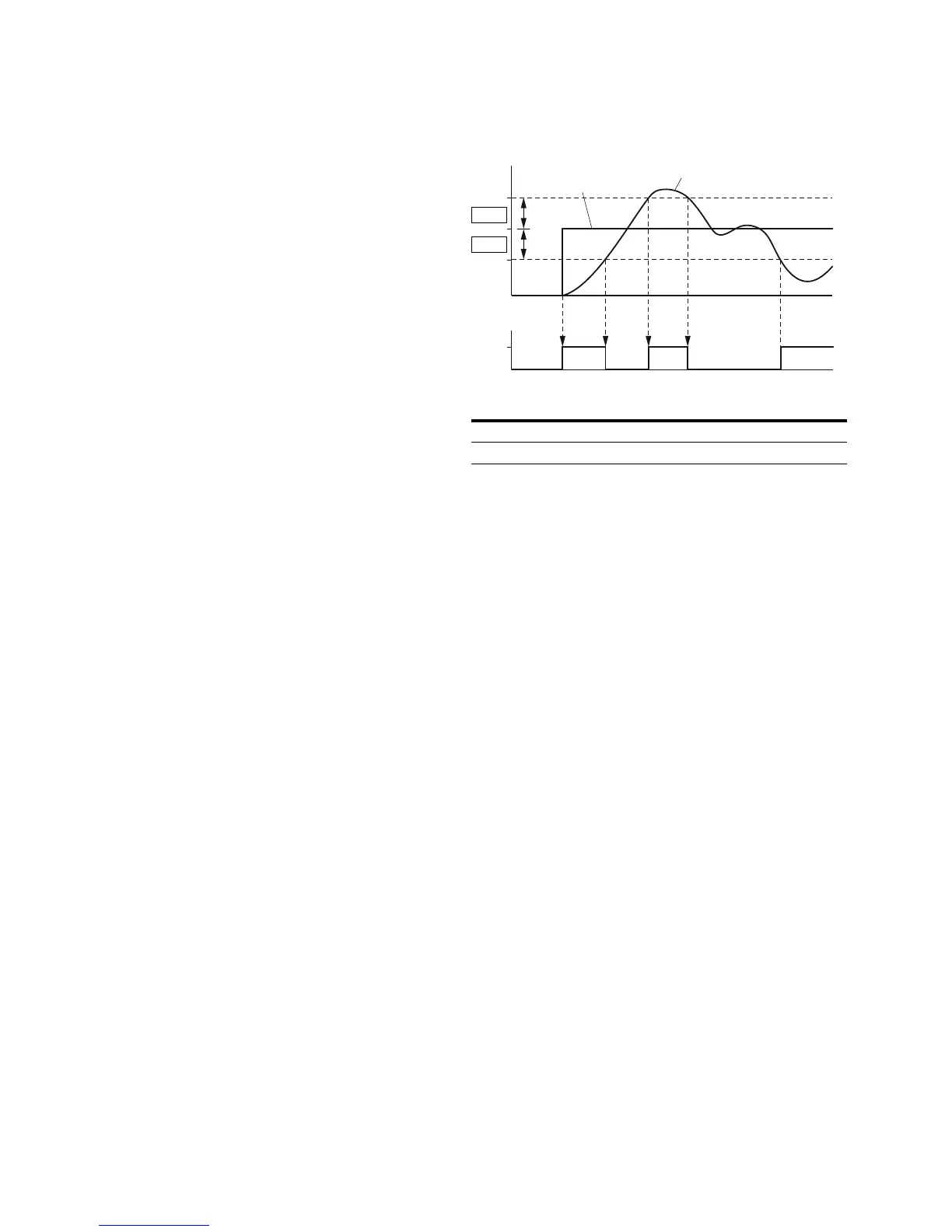
Function Chart for OD (PID System Deviation)
Feedback Value Check Signal (FBV)
The FBV (Feedback Value Check) signal is issued when:
●
The actual value (PV) drops below the lower limit value
(P9.16) in RUN mode. It remains active until:
●
The actual value exceeds the upper limit value (P9.15)
●
The frequency inverter changes from RUN mode to STOP
mode (deceleration with the set ramp time)
Item
Number Description
1 Setpoint value
2 Actual value
OD
P9.17
P9.17
1
2

 Loading...


