Serial Interface (Modbus RTU)
M-Max Series Adjustable Frequency Drive MN04020003E—October 2013 www.eaton.com 131
Serial Interface (Modbus RTU)
General Information About Modbus
Modbus is a centrally polled bus system in which a so-called master (PLC) controls the entire
data transfer on the bus. Cross-traffic between the individual slaves is not possible.
Each data exchange is initiated only on request of the master. Only one request can be issued
on the cable. A slave cannot initiate a transfer but only react to a request with a response.
Two types of dialog are possible between master and slave:
●
The master sends a request to a slave and waits for a response
●
The master sends a request to all slaves and does not wait for a response (broadcast)
More information on Modbus can be found under www.modbus.org.
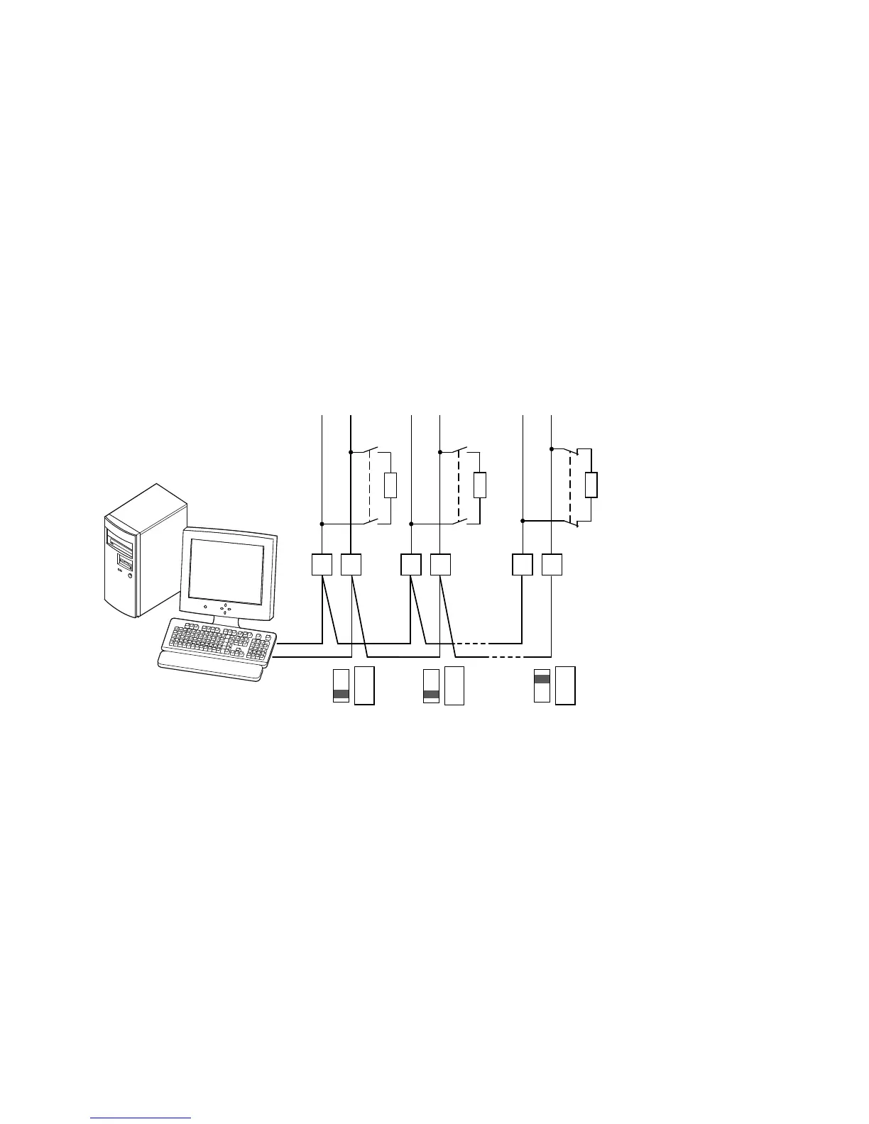
Communications in a Modbus Network
Modbus Network with M-Max
The figures shows a typical arrangement with a host computer (master) and any number
(maximum 31 slaves) of frequency inverter M-Max (slaves). Each frequency inverter has a
unique address in the network. This addressing is executed individually for each M-Max via
system parameter S2.3 and is independent of the physical connection (position) in the network.
Serial Interface A-B
The electrical connection between master and the slaves
connected in parallel is implemented via the serial interface
A-B (A = negative, B = positive) with a shielded RS485
twisted pair cable.
The position of the connection terminals in the M-Max for
the serial interface A-B (see figure on Page 45).
The M-Max’s built-in RS-485 port supports the Modbus RTU
protocol and therefore allows a direct network connection
without an additional interface module.
The network cable must be provided at each physical end
(last station) with a bus termination resistor (120 ohms) in
order to prevent signal reflections and the resulting transfer
errors. This necessary resistor is already integrated in the
M-Max frequency inverter and is switched on via
microswitch S4 (see figure on Page 45).
Host Computer
A
B
A
B
A
B
S4
120 ohms
12 n
S4
120 ohms
S4
120 ohms
RS485
– Term
RS485
– Term
RS485
– Term

 Loading...


