Installation
26 M-Max Series Adjustable Frequency Drive
MN04020003E—October 2013 www.eaton.com
Installation
Introduction
This chapter provides a description of the installation and the
electrical connections for the frequency inverter M-Max series.
While installing and/or assembling the frequency inverter,
cover all ventilation slots in order to ensure that no foreign
bodies can enter the device.
Perform all installation work with the specified tools and
without the use of excessive force.
Installation Instructions
The instructions for installation in this manual apply for M-Max
series frequency inverters under protection type IP20.
In order to meet the requirements in accordance with
NEMA 1 (IP21), you must, depending on the size of the
housing, use the optional housing accessories
MMX-IP21-FS1, MMX-IP21-FS2 or MMX-IP21-FS3.
The required installation instructions are shown in the setup
instructions AWA8230-2417.
Mounting Position
Mounting Position (FS1–FS3)
An installation that is turned by 180° (stood on its head) is not
permitted.
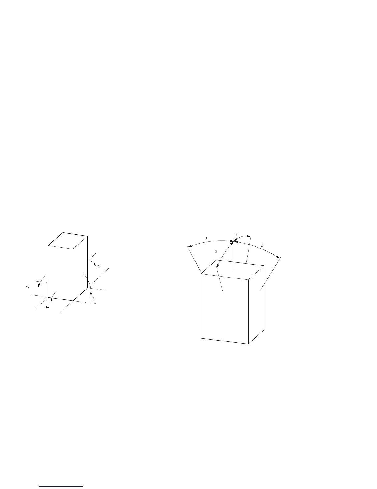
Mounting Position (FS4 and FS5)
An installation that is turned by 180° (stood on its head) is not
permitted.
The vertical mounting position may be tilted by up to
30 degrees.
90°
90°
90°
90°
30°
30°
30°
30°

 Loading...


