Installation
36 M-Max Series Adjustable Frequency Drive MN04020003E—October 2013 www.eaton.com
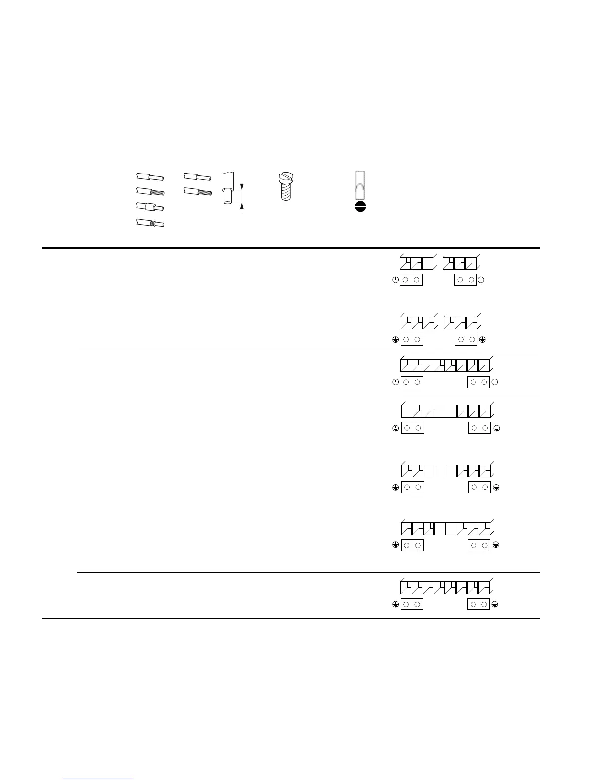
Arrangement and Connection of the Power Terminals
The arrangement and size of the connection terminals depends on the construction of the
power section (FS1, FS2, FS3).
The cross-sections to use in the connections, the tightening torques for screws and
respective fuses are listed in the following table.
Arrangement and Size of the Connection Terminals
Part
Numbers mm
2
AWG mm in Nm ft-lbs mm Terminal Configuration
FS1 MMX12AA1D7_
MMX12AA2D4_
MMX12AA2D8_
0.2–2.5 24–12 8 0.31 0.5–0.6 0.37–0.44 0.6 x 3.5
MMX32AA1D7_
MMX32AA2D4_
MMX32AA2D8_
0.2–2.5 24–12 8 0.31 0.5–0.6 0.37–0.44 0.6 x 3.5
MMX34AA1D3_
MMX34AA1D9_
MMX34AA2D4_
0.2–2.5 24–12 8 0.31 0.5–0.6 0.37–0.44 0.6 x 3.5
FS2 MMX11AA1D7_
MMX11AA2D4_
MMX11AA2D8_
MMX11AA3D7_
0.2–2.5 24–12 8 0.31 0.5–0.6 0.37–0.44 0.6 x 3.5
MMX12AA3D7_
MMX12AA4D8_
MMX12AA7D0_
0.2–2.5 24–12 8 0.31 0.5–0.6 0.37–0.44 0.6 x 3.5
MMX32AA3D7_
MMX32AA4D8_
MMX32AA7D0_
0.2–2.5 24–12 8 0.31 0.5–0.6 0.37–0.44 0.6 x 3.5
MMX34AA3D3_
MMX34AA4D3_
MMX34AA5D6_
0.2–2.5 24–12 8 0.31 0.5–0.6 0.37–0.44 0.6 x 3.5
M3
L1
L2/N
U/T1
V/T2
W/T3
L1
L2/N
U/T1
V/T2
W/T3
L3
L1
L2/N
U/T1
V/T2
W/T3
L3
R+ R–
L3
L2/N
U/T1
V/T2
W/T3
L1
L2/N
U/T1
V/T2
W/T3
L1
L2/N
U/T1
V/T2
W/T3
L3
L1
L2/N
U/T1
V/T2
W/T3
L3
R+ R–

 Loading...


