the way this “trigger” can be interpreted by the system, but usually a message is printed in
response to a signal from the photocell.
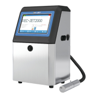
The photocell should be mounted upstream of the print head (so it detects the product before the
product reaches the print head), as close to the print head as possible and at a distance from the
product which gives consistently reliable triggering when a product passes it. A delay between the
photocell being triggered and the print taking place can be set by a menu command, to aid fine
adjustment of print positioning on the product.
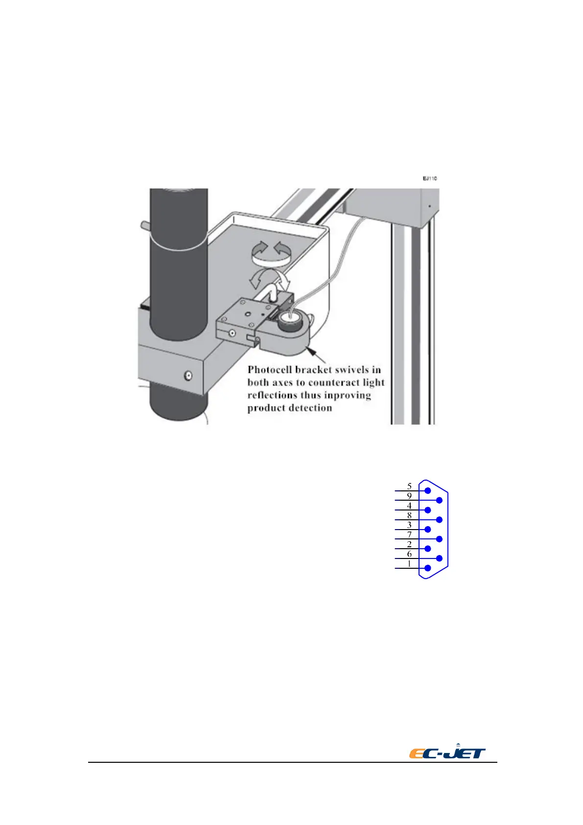
1.6.1 Photocell Connections
The photocell is connected to the system via a 9-pin D - Type connector. The function of each pin
is described below:
Pin 1 + 24volts
Pin 2 0 volts
Pin 3 + 5 volts
Pin 6 Next Object Signal
If the photocell has a screened conductor, it should be connected to the shell of the D - Type
connector and to the printer chassis at the printer end of the cable (it must not be connected to D
volts).
CAUTION: Electromagnetic Compatibility performance may be compromised by the use of
unsuitable photocells. Use only EC-JET approved accessories.
1.7 Setting up the Shaft Encoder
Shaft encoders are recommended for production lines where variable speed is likely. A shaft
encoder generates a pulse for a fixed distance of product movement. This can be used to produce