EasyManuals Logo

EDAN F15 Series Service Manual

EDAN F15 Series
80 pages
To Next Page IconTo Next Page
To Previous Page IconTo Previous Page
Page #56 background imageLoading...
Page #56 background image
F15 Series Fetal & Maternal Monitor Service Manual Modules’ Malfunction Verification
- 45 -
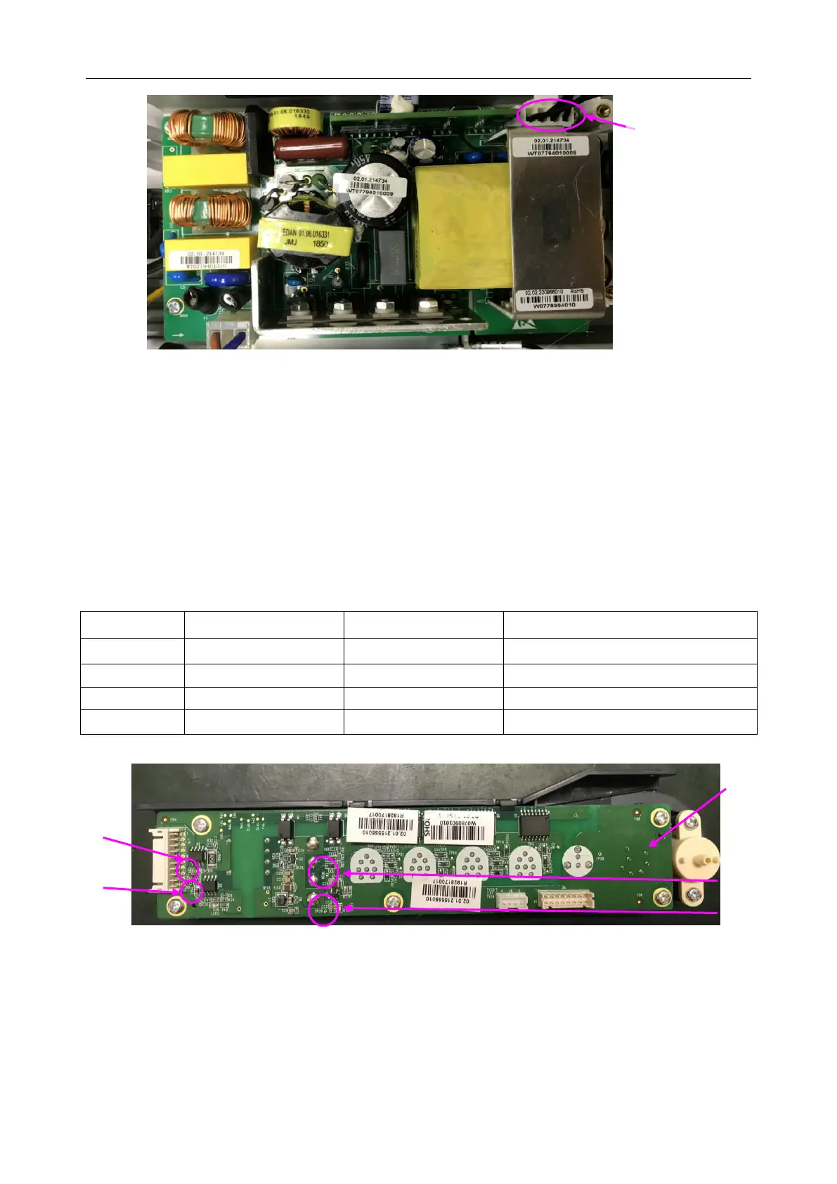
8.5 Verifying Malfunction of EDAN Transducer Socket Board
(wired model only)
To verify the EDAN transducer socket board,
1) Open the main unit using the procedures described in section 9.3.
2) Switch on the monitor. (Powered by AC or battery.)
3) Measure the voltage to earth of the pins listed below, using a multimeter:
Item
Reference Pin
Test Pin
Reference result
1
TP24(GND)
TP23
4.75~5.25V
2
TP24(GND)
TP27
11.4~12.6V
3
TP25(FGND)
TP26
5.23-5.78V
4
TP25(FGND)
TP28
4.75-5.25V
EDAN Transducer Socket Board
4) If any one of the results exceeds the reference range, the EDAN transducer socket board
defection is confirmed. Replacement of the board is recommended.
1
TP23
2
TP27
EDAN
Transducer
Symbol
4
TP28
3
TP26
1
st
/2
nd
/3
rd
/4
th
pin of J3
from left to right

Table of Contents

Other manuals for EDAN F15 Series

Questions and Answers:

Question and Answer IconNeed help?

Do you have a question about the EDAN F15 Series and is the answer not in the manual?

EDAN F15 Series Specifications

General IconGeneral
BrandEDAN
ModelF15 Series
CategoryMonitor
LanguageEnglish

Related product manuals