Chapter 1
| Switch Description
Overview
– 12 –
USB Port
A USB port is provided on the switch front panel. This port is for transferring
configuration files from a USB storage device to the switch’s flash memory. For
more information, see “How to Connect to the USB Port” on page 52.
Reset Button
Pressing the reset button on the front panel causes the switch to preform a hard
reset. For more information, see “How to Reset the Switch” on page 53.
System LEDs
For information on system status LED indicators, see “Understanding the System
Status LEDs” on page 48.
Port LEDs
For information on port status LED indicators, see “Understanding the Port Status
LEDs” on page 35.
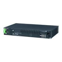
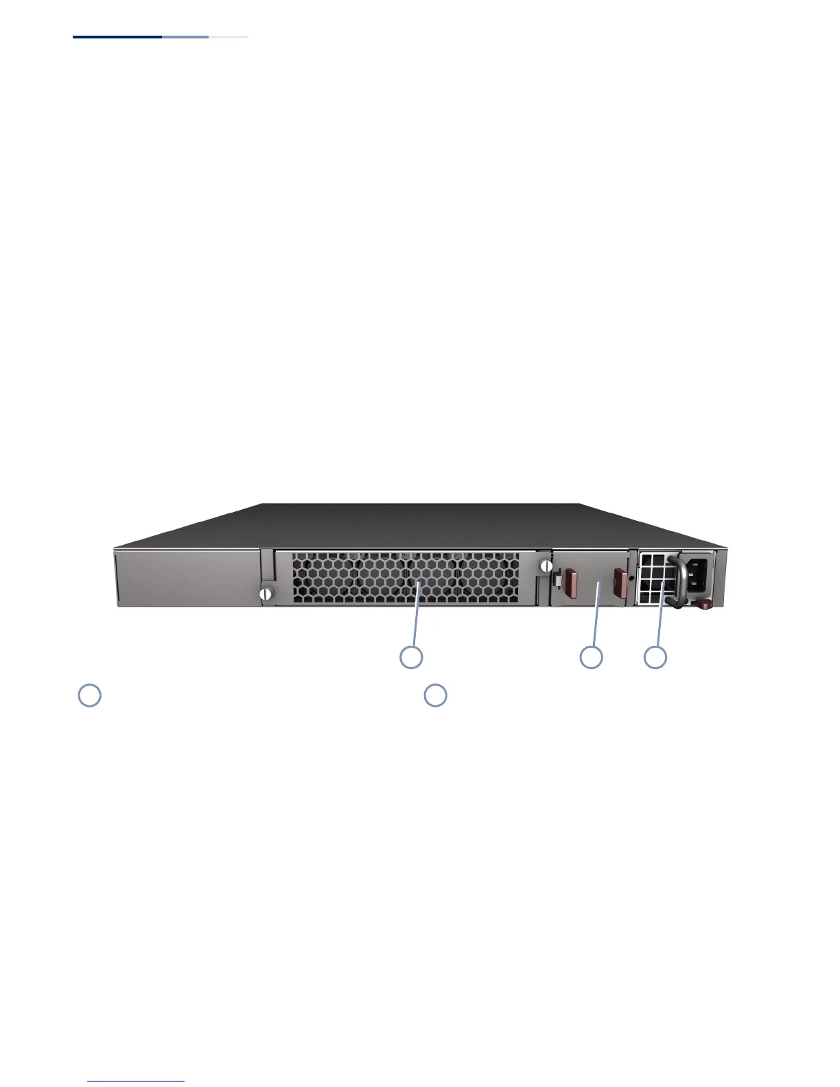
Figure 2: Rear Panel
Power Supply Modules
The switch supports dual hot-swappable AC power supply units (PSUs). You can
install up to two PSUs with matching airflow direction in the switch. For more
information on the switch power supplies, how to install them, and how to power-
on the switch, see “Power Supply Modules” on page 29.
Fan Tray Module
The fan tray module provides air cooling for the switch system. For more
information, see “Switch Cooling Requirements” on page 26.
Fan Tray Module Power Supply Modules

 Loading...