EasyManuals Logo

Edge-Core AS5610-52X Installation Guide

Edge-Core AS5610-52X
58 pages
To Next Page IconTo Next Page
To Previous Page IconTo Previous Page
Page #48 background imageLoading...
Page #48 background image
Chapter 6
| Switch Management
Understanding the System Status LEDs
– 48 –
Understanding the System Status LEDs
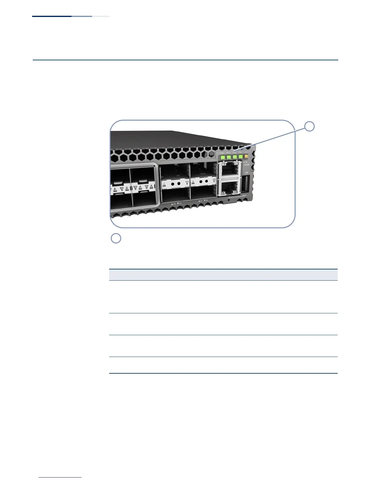
The switch includes a display panel of key system LED indicators. The LEDs, which
are located on the front panel, are shown below and described in the following
table.
Figure 26: System LEDs
System Status LEDs.
Table 11: System Status LEDs
LED Condition Status
PSU1/PSU2 On Green Power supply 1/2 is installed and operating normally.
On Amber The power supply has detected a fault.
Off The power supply unit is not installed.
Diag On Green The system diagnostic test has completed successfully.
On Amber The system self-diagnostic test has detected a fault.
Fan On Green Fans are operating normally.
On Amber A fan failure has been detected.
Loc Flashing Amber Activated through remote software to assist identification
of the switch unit within a rack.
1
1

Table of Contents

Other manuals for Edge-Core AS5610-52X

Questions and Answers:

Question and Answer IconNeed help?

Do you have a question about the Edge-Core AS5610-52X and is the answer not in the manual?

Edge-Core AS5610-52X Specifications

Operating Environment IconOperating Environment
operating temperature0° C to 40° C
storage temperature-40° C to 70° C
operating humidity5% to 95% (non-condensing)
Power IconPower
AC input voltage100-240 VAC
AC input frequency50-60 Hz
AC input current6-3 A
DC output 5V3 A
DC output 12V33 A
power consumption165 Watts maximum
maximum current at 100 VAC6 A
maximum current at 240 VAC3 A
power supply power400 Watts @ 240V/100V per module
Weight and Dimensions IconWeight and Dimensions
width438.4 mm
depth473 mm
height43.4 mm
weight8.395 kg
power supply width54.5 mm
power supply depth220 mm
power supply height40.25 mm

Related product manuals