Chapter 2
| Installation Overview
Switch Installation Tasks
– 20 –
Install Power Modules and Power On
Install power modules, then power on. The switch supports up to two PSUs that
have a matching airflow direction as the installed fan tray.
Caution:
The switch includes plug-in power supply and fan tray modules that are
installed into its chassis. All installed modules must have a matching airflow
direction. That is, all modules must have a front-to-back (F2B) airflow direction, or
all modules must have a back-to-front (B2F) airflow direction. The airflow direction
of PSUs and fan trays is indicated by labels on the modules.
Go to the chapter “Power and Grounding”
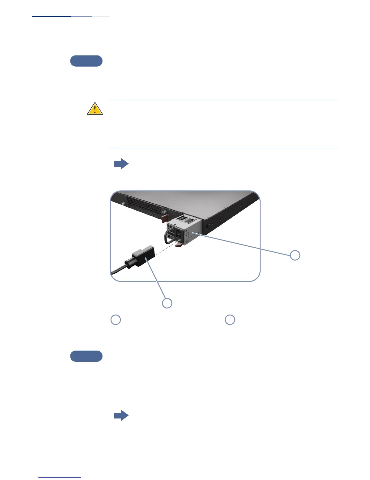
Figure 8: Connecting AC Power
Verify Switch Operation
Verify basic switch operation by checking the system LEDs.
When operating normally, the PSU1/PSU2, Diag, and Fan LEDs should all be on
green. If any of the LEDs are on amber, see “Diagnosing LED Indicators” on page 54
Go to the section “Understanding the System Status LEDs”
Install one or two universal AC power
modules in the switch.
Connect an external AC power source
to the modules.

 Loading...