149
support@edgeovens.com
Technical Support: +1 (724) 628 3050
SERVICE
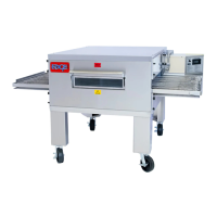
To test, measure the resistance between post 1 and 2 on each coil (Figure 4-45).
These coils do naturally become HOT to the touch during normal operation.
The BASO ignition module performs a test on the PV (Pilot Valve) and the MV (Bypass/
High Flame Valve) connections at start up. A 3 x RED FLASH ignition module (IM)
fault indicates a Pilot Valve connection or coil failure; whereas, a 4 x RED FLASH fault
indicates a Bypass coil failure.
If a coil measures correctly and voltage is present to the coil but the valve is not opening,
ensure the supply pressure to the valve is not greater than 37mbar/14.8inW.C. before
condemning the valve.
MAIN VALVE COILS
PART FAILURE VERIFICATION
CONTROLS AND ASSEMBLIES (CONTINUED)
1 2
3
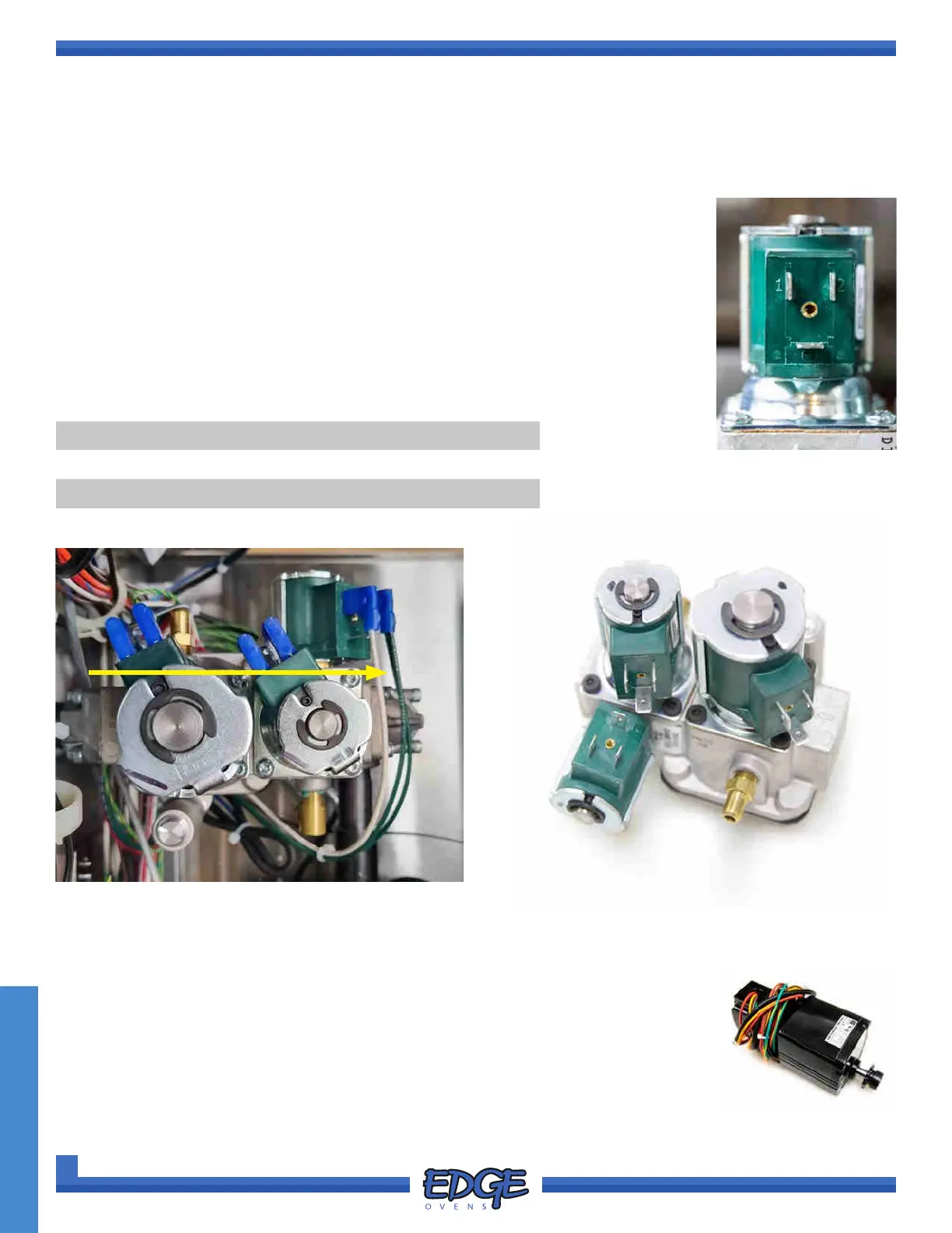
FLOW DIRECTION
FIGURE 4-46
The conveyor motor is powered and monitored by the control system (MC1 and MC2).
This is a 3 Phase, 24VDC motor with Hall Effect feedback. Do not attempt to power
the motor by other means.
1. If the motor is bound, this may indicate a lubrication problem from staging (new
installs or prolonged idle periods more than 30 days). A slight manual rotation of
the sprocket will resolve this.
2. Use the ‘EXPORT’ feature to obtain a logle from the oven to thoroughly diagnose
conveyor motor problems which fall outside of the ‘idle’ condition mentioned.
CONVEYOR MOTOR
1
2
3
FIGURE 4-45
COIL APPLICATION COIL SIZE RESISTANCE
1. Pilot Valve 15VA COIL 6M Ω ~ 8.5M Ω
2. Main (High Flame) Valve 10.5VA COIL 5M Ω ~ 6M Ω
3. Bypass Valve 10.5VA COIL 5M Ω ~ 6M Ω