34
support@edgeovens.com Technical Support: +1 (724) 628 3050
INSTALLATION
OVEN ASSEMBLY
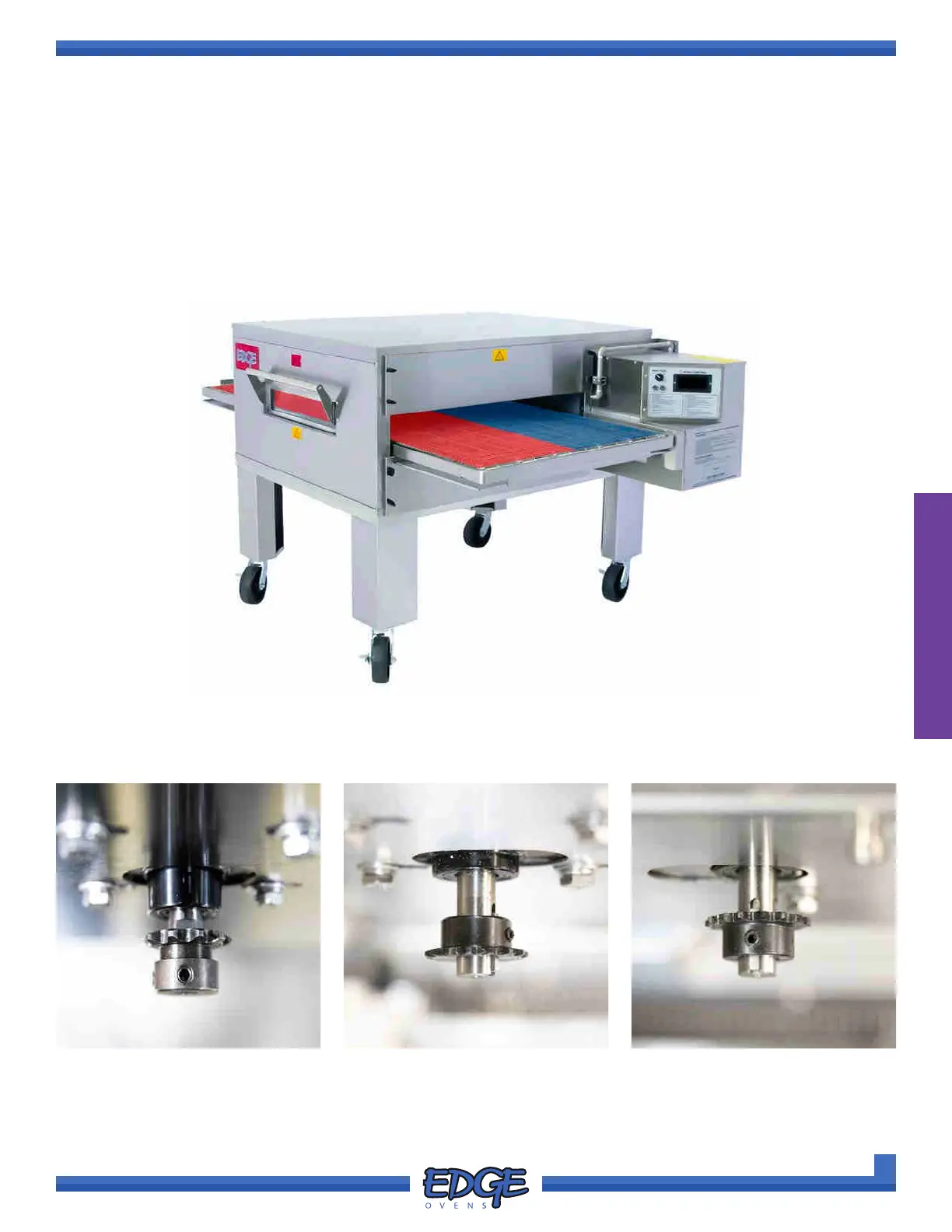
SPLIT-BELT CONVEYOR DRIVE SYSTEM ASSEMBLY
Each motor in a split-belt system has a specic sprocket size and orientation. ALL sprockets are keyed with a
1/2” bore.
FIGURE 2-71
NON SPLIT-BELT SPROCKET
10 TOOTH, 35 PITCH
(2 x ALLEN SET SCREWS)
SPLIT-BELT REAR MOTOR
15 TOOTH, 25 PITCH WITH
REVERSED ORIENTATION
(2 x ALLEN SET SCREWS)
SPLIT-BELT FRONT MOTOR
15 TOOTH, 25 PITCH
(2 x ALLEN SET SCREWS)
FIGURE 2-72 FIGURE 2-73
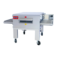
A split-belt conveyor, allows the oven operator to run two different conveyor speeds through the same oven
chamber. Much like the standard conveyor belt, conveyor drive chain tension should be assessed as well
sprocket orientation and alignment.
Each channel of a split-belt conveyor, is driven by its own dedicated conveyor motor. The rear belt (denoted
by blue channel), is driven by the motor closest to the oven mouth and is held in place by four (4) 1/2” x 1/4-20
bolts. The front belt (denoted by the red channel) is driven by motor positioned further to the right hand side of
the oven and is secured by three (3) 1/2” x 1/4-20 bolts.