54
support@edgeovens.com Technical Support: +1 (724) 628 3050
INSTALLATION
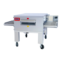
FIRE SUPPRESSION
FIGURE 2-127
1. Begin by separating each of the
sided pipework assemblies by
disconnecting the union joints.
(Figure 2-127)
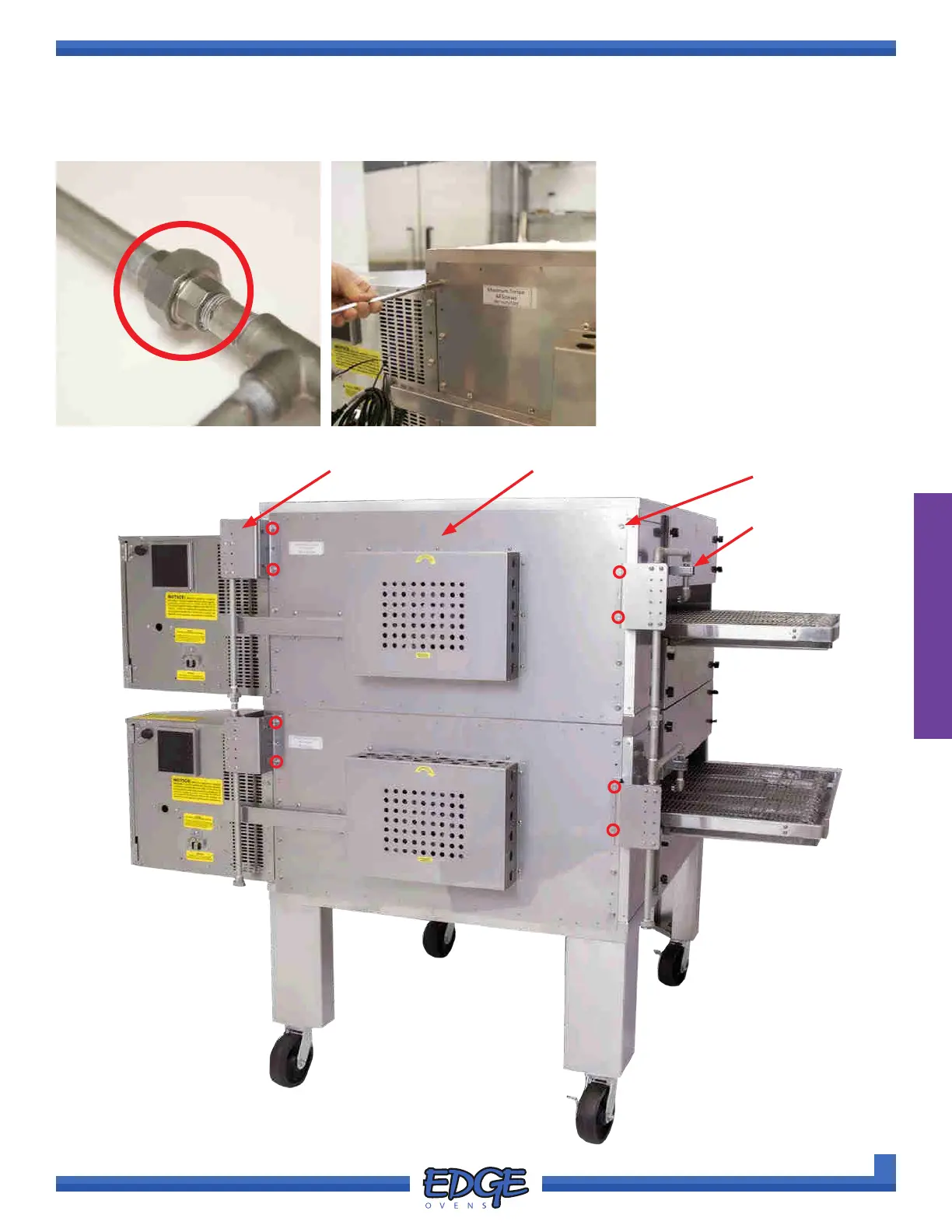
2. Identify the ten (10) 3/8” hex-
head screws which secure the
oven back. Using a 3/8” socket
and ratchet remove screw 1 and
2 on the control cabinet side and
screw 7 and 8 on the opposing
side. (Figure 2-128 and 2-129)
FIGURE 2-129
1
2
3
4
5
6
7
8
9
10
A
3
A
1
A
2
A
4
1
2
3
4
5
6
7
8
9
10
FIGURE 2-128
3/8” HEX-HEAD
FASTENERS
OVEN BACK‘A’ BRACKETS
‘B’ BRACKETS
PIPE & BRACKET INSTALL