24V(+)P15(1) Wake
P10(5)
V(-)P15(3)
FAN P10(1)
TC(+)P11(1)
TC(-)P11(2)
UI(Comm)P7 or P8
GND P9(7,11,12)
TACH(in)P2(2)
24V(in)P9(6)
HFV(out)P9(15)
24V(out)P9(3) HFV(sense)P9(8)
HFV(in)P9(16) BPV(out)P9(2)
BPV(in)P9(1) BPV(sense)P9(9)
Optional, Split-Belt
AS1
V
F
D
*
F
i
g
u
r
e
3
P
H
2
a
/
2
b
T B
T B
GND (8)
HE1 (5)
HE2 (4)
HE3 (3)
HE+ (10
HE- (9)
PhA (6)
PhB (1)
PhC (2)
L or
M1
M2
N or
M3
t
BRN/24V GND
MV
24V PV
Sense
Spark
HFV
PV
T1
TP
S1
CB1
PS
OFD
PB
G
N +V
L -V
CB2
BPV
S2
P6
24V(+)P15(1) Wake
P10(5)
V(-)P15(3)
UI(Comm)
P7 or P8
GND (8)
HE1 (5)
HE2 (4)
HE3 (3)
HE+ (10
HE- (9)
PhA (6)
PhB (1)
PhC (2)
P6
MC1
MC2
M3
USB
UI
IP-IM
*Figure 4
UI
4
-
w
i
r
e
4-wire
Molded
3-wire
CD-942-026-05
Lf
Nf
*Figure 4
R1
2
4
6
8
0
1
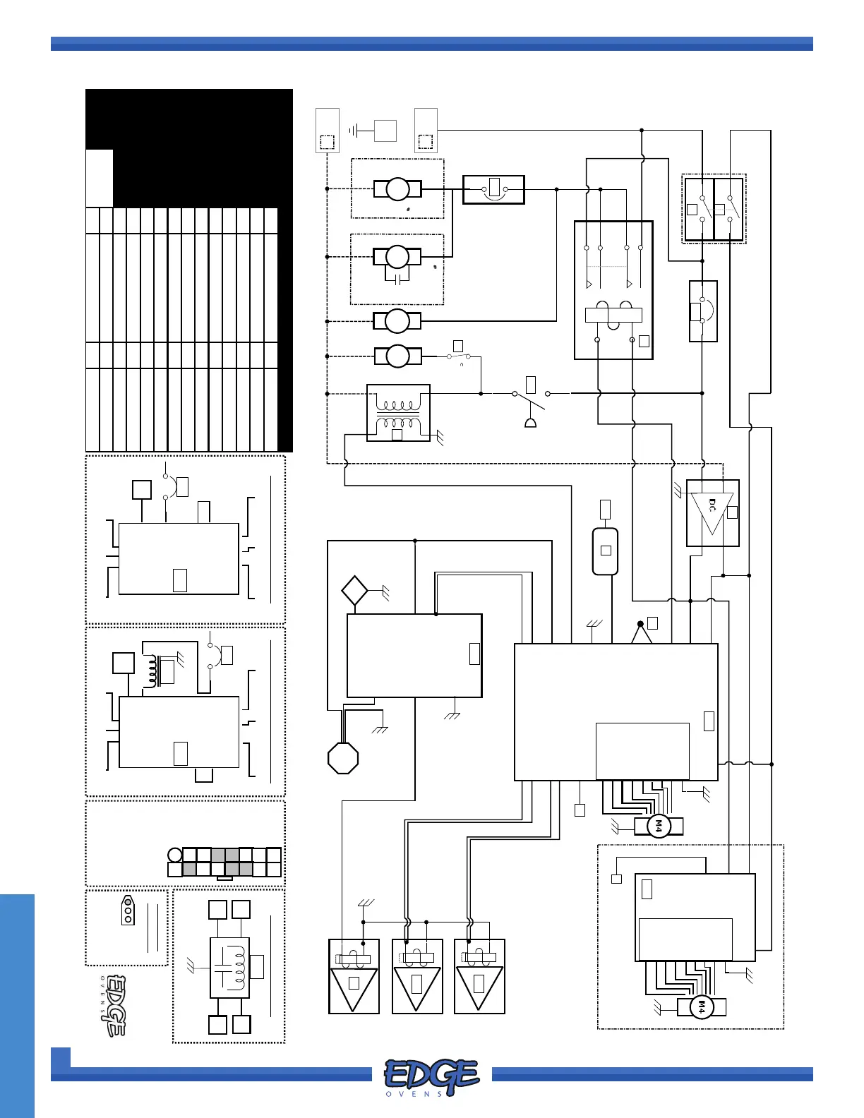
EDGE, Bypass ON/OFF, 2022
MF&B Restaurant Systems, Inc
AS1 Air Switch Px(x) Plug number (Pin)
119 ICMI RD, STE 300
BPV Bypass Valve PS 24V Power Supply
Dunbar, PA, USA 15431
CB1 Circuit Breaker 1, 3A PV Pilot Valve
Drawing No.: G2.5-ELEC-04
CB2 Circuit Breaker 2, 10/ 15A R1 Fan Relay
Date: 06/2022
HFV High Flame Valve S1 Switch 1, MAINS
Author: A.H.
IP-IM Int. Pilot - Ign Module S2 Switch 2, Wake
M1 Main Fan Motor T1 24V Transformer
M2 Cooling Fan TC Thermocouple, J
Firmware Version
M3 Burner Blower TP Thermal Protect
MC34+, UI33+
M4 Conveyor Motor UI User Interface
MC1 Machine Control, Main USB Service Port
MC2 Machine Control, ( sb) *EM1 MAINS Filter
Chassis:
2C
OFD Optical Flame Detect *EM2 Line Reactor
PB Pilot Burner *VFD Var Freq Drive
N.A. Frequency Driven Models
M1 (1)
M1 (2) M1 (3)
N
CB2
MC1.P1(3)
MC1.P1(2)
MC1.P1(1)
U V W
TA TB COM
24V (1)
DI1 (11)
L2
N
L1
VFD
Modbus
Cable
MC1.P1(1)
WORLD Frequency Driven Models
M1 (1)
M1 (2) M1 (3)
Nf
CB2
MC1.P1(3)
MC1.P1(2)
U V W
TA TB COM
24V (1)
DI1 (11)
L2
L1
VFD
EM2
Modbus
Cable
MC1
P9
1
2
3
4
5
6
7
8
9
10
11
12
13
14
15
16
8- Rd
7- Gr/Yl
6- Or
3- Or/Wh
2- Gr
1- Rd/Wh
16- Rd/Wh
15- Rd
12- Gr/Yl
11- Gr/Yl
9- Gr
Main Motor
Circuit Plug
1- Bw
2- Wh
3- Gr/Yl
Figure 5
WORLD MAINS Filtering
Lf
L
(In) (Out)
N
Nf
EM1
Figure 3
Figure 2a
Figure 2b
Figure 1
TC
Figure 4
P
S
C
C
B
2
=
1
5
A
1
P
H
M1
1/3HP
3/4HP
C
a
b
in
e
t M
o
u
n
te
d
7
.
5
u
F
3
7
0
v
Alternate Part
CB2=10A
Variant
Part