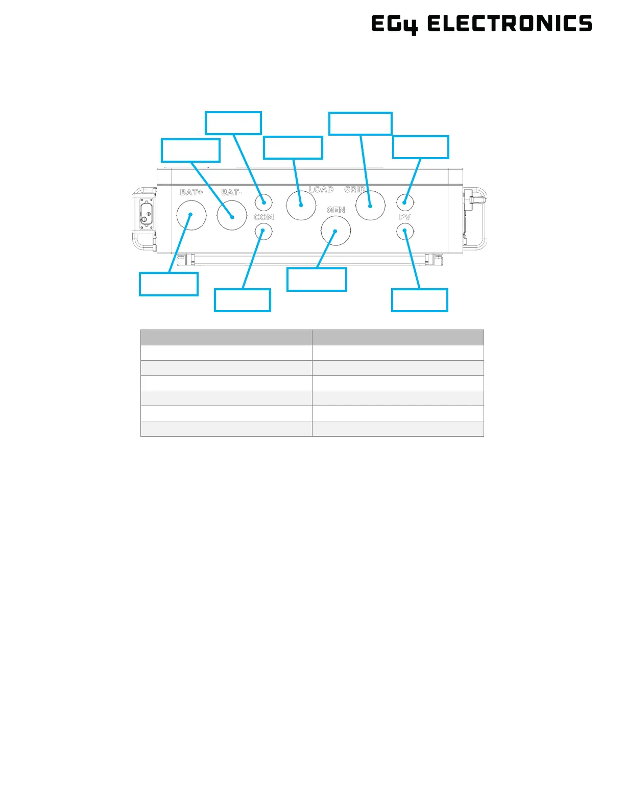
5.3 CABLE BOX KNOCKOUTS
The image below represents the bottom view of the cable box area with knockout hole sizing shown
in nominal trade sizes.
U.S. NOM. TRADE SIZE ACTUAL KO SIZE
5.4 OPERATION OVERVIEW
The information below provides a high-level overview of the general operation of the inverter.
• This is an off-grid inverter that does not have the ability to sell power back to the grid but can
utilize grid power for battery charging and pass-through to loads.
• For the inverter to power on, it must be connected to a supported DC and/or AC power
source. The minimum supported voltage for each source must be met as described in the
technical specifications table.
• When the inverter’s power switch on the right side of the unit is moved to the “on” position,
the front display will illuminate; the inverter can be configured using the front display. The
inverter must be set up for Wi-Fi connectivity before remote software can be used.
• The “EPS” switch, found on the left side of the inverter, controls the output current to the
“Load” terminals. Once the “EPS” switch is set to the “on” position, the “Load” terminals can
output current.
• The “Smart Load” terminal is controlled by software and can output current based on user
configured time and/or set conditions or accept an existing AC coupled system.
• If PV or battery voltage is present, the inverter can output current to the “Load” or “Smart
Load” terminals as determined by the configuration of the front panel or remote software.
• To stop AC output on the load terminals, either turn the EPS switch to the “off” position, turn
the load or smart load breaker to the “off” position, or use the Emergency Stop button if
equipped.