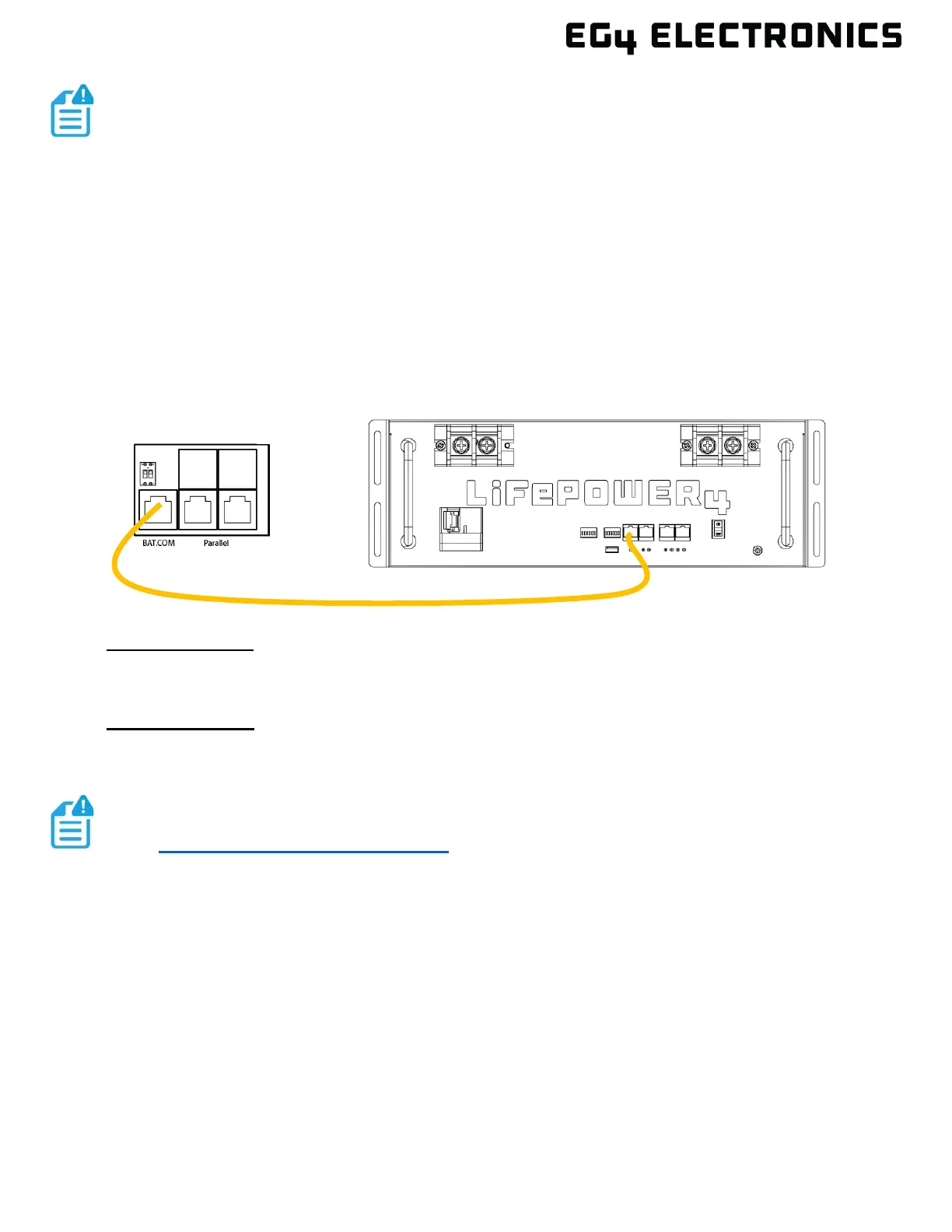
4. Connect the included orange communications cable between inverter and battery
communications port (either the CAN or RS485, depending on make/model of battery). See
example diagram below:
Multiple Inverters: If more than one inverter is installed, connect the battery communication cable
to the inverter that will be used as the master inverter. All additional inverters will communicate with
the master inverter through the parallel communication cable for all needed battery information.
Multiple Batteries: When using more than one battery, use the communication cable supplied with
each battery to interconnect each battery, including the master battery. This allows the master
battery to gather all battery data and provide it to the master inverter.
7.3 AC CONNECTIONS
The inverter supports 100 amps of AC current on the Grid and EPS Load port. The loads (EPS)
output can receive AC current directly from the AC input (bypass mode) or current inverted from PV
and battery. There is also a smart load port that can be configured to either be a smart load output or
an AC Coupled solar input. smart loads can be programmed to either load shed, or power shed for
individual appliances or whole subpanels. This smart port is either opened or closed based on the
port configuration which is user defined.
It is recommended to install a separate AC breaker between inverter and AC input power source;
this will ensure the inverter can be disconnected during maintenance and fully protected from over
current AC input.
NOTE:
When installing multiple inverters in parallel and using the share battery
feature, the battery or battery bank must be connected to each inverter so the
current can be evenly shared to each inverter. The positive cable from the
battery or battery bank to each inverter should be of equal length. If a busbar is
used between the battery bank and the inverter, the cable from the busbar to
each inverter should be equal lengths. Each negative cable should be of equal
length as well. Using equal length positive cables and equal length negative
cables supports equal amperage to each inverter.
NOTE:
See https://www.eg4electronics.com/ for detailed information with configuring,
connecting, and troubleshooting EG4
®