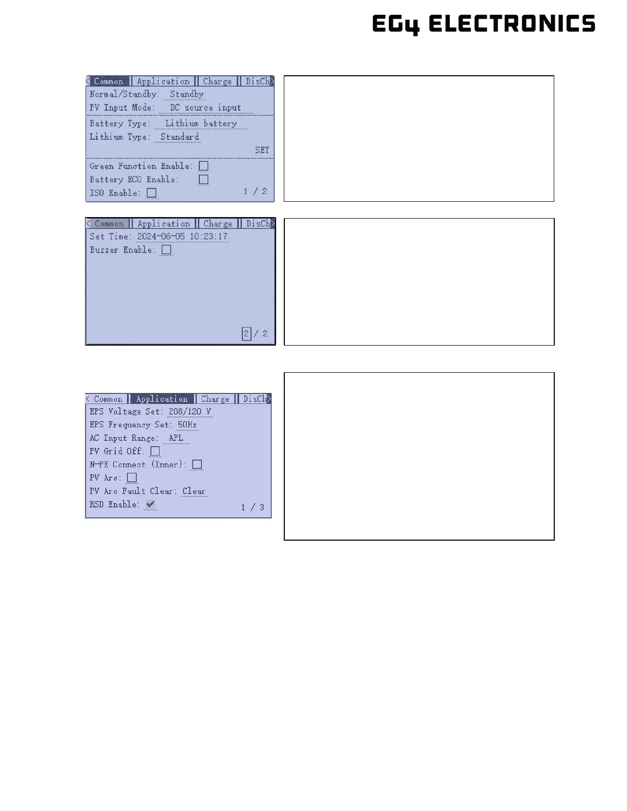
• Common Tab (Pages 1 and 2)
• Application Tab (Page 1)
10. Verify the loads panel is ready to accept current from the inverter. Set the input breaker at the
loads panel to the closed (ON) position.
11. Set the output breaker on inverter to the closed (ON) position. Turn the EPS output switch to
the closed (ON) position. The inverter should now be providing current to the loads panel.
8.2 MULTIPLE INVERTERS
The EG4
®
12000XP Off-Grid inverter supports up to 6 units connected in parallel to reach a capacity
of up to 72kW. To successfully connect inverters together in a parallel configuration, verify the
following:
• A single string of solar panels cannot be shared between inverters.
• Each inverter must be cabled to the same single battery or battery bank.
• In order to support proper ventilation and cooling, the inverters are installed with required
clearances as shown in section 5.
PV Input Mode: select one of the following:
• DC source input
• PV1 and PV2 independent
• PV1 and PV2 parallel
Battery Type: select No battery, Lead Acid or Lithium
Lithium Type: select a supported brand of battery.
(Select “0:EG4” if using an EG4
®
lithium battery.)
Set Time: Set or verify the current date and time.
Buzzer Enable: Remove the check mark to disable the
beep when the display buttons are pressed.
EPS Voltage Set: Verify the voltage is set to 240Vac
EPS Frequency Set: Verify frequency is set to 60Hz
AC Input Range: Choose APL or UPS. UPS: supports
AC voltage range 170V – 280V and APL supports
voltage range from 90V – 280V. UPS will have a faster
switchover time.
N-PE Connect: Normally unchecked when using AC
input from the grid. If there is not grid input, verify where
the neutral ground bond is setup. Consult with a
qualified electrician for help if needed.