AC Coupling Settings:
The “AC Couple” setting must be enabled when connecting an existing on-grid system to the smart
load port. It is recommended to keep the “Start SOC(%)/Voltage(V)” and the “End
SOC(%)/Voltage(V)” within 5 – 10% of each other for optimal operations when utilizing AC coupling
(see section 10.7 for settings through the LCD, see section 12.4 for settings through Monitor
Center).
11. FRONT PANEL DISPLAY
The user can wake up the LCD screen by simply
pressing the Enter button. System status, real-time
power, and daily and accumulated energy
information can all be conveniently viewed on the
inverter’s LCD screen. Additionally, users can check
the alarm and fault record on the display for
troubleshooting.
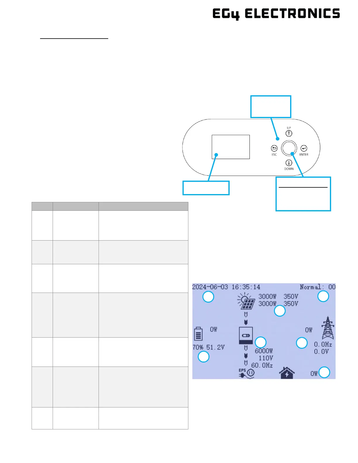
11.1 DISPLAY OVERVIEW
1
General
Information
Display Area
Displays the current time/date
by default.
2
Photovoltaic
(PV) Data
Displays the current PV data.
3
Working status
text
display area
This area displays the status
code of the inverter, including
rated running status text, errors
4
Battery
information
and data
This area displays the battery
type, (lithium or lead acid),
voltage, SOC, and input/output
power.
5
UPS/EPS
output
information
This area displays LOAD
voltage, frequency, power.
6
Grid and
Generator
information
Displays the grid information for
voltage,
frequency, input or output
power, the Generator
information of voltage,
7
Load
consumption
consumption by the load in the
Green = Normal
Yellow = Warning