7. CABLE CONNECTIONS
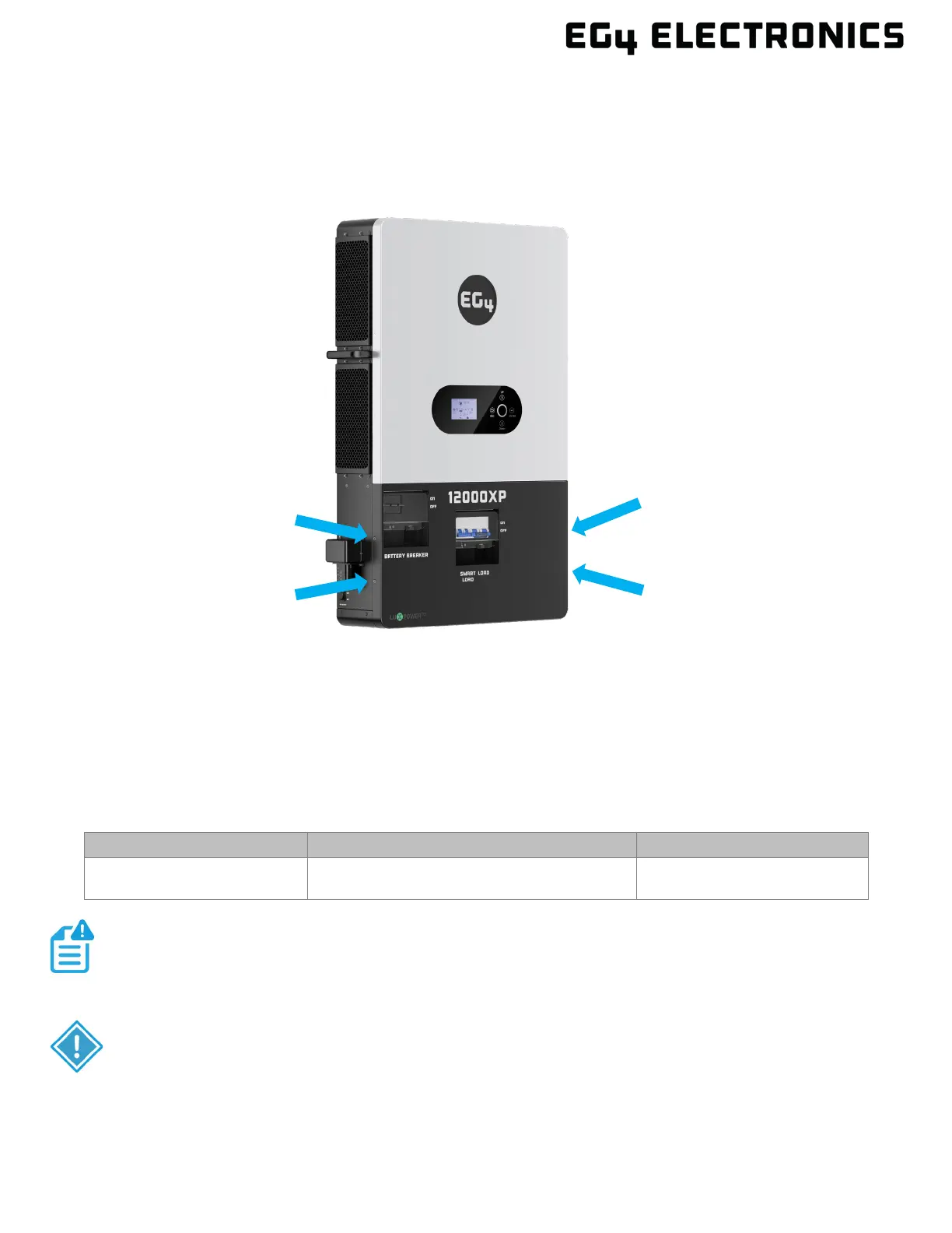
To expose the cable box area, remove the bottom cover by removing the 4 screws identified in the
image below. Once the cover is removed, follow the sections below for connecting the wiring for PV,
AC, Battery, Generator, RSD, and Parallel cables. Before connecting any wiring to the inverter, verify
each wire is not carrying voltage using a multimeter.
7.1 PV CONNECTIONS
The inverter is equipped with two MPPT controllers, each with 2 sets of connectors per controller.
The two inputs can support two strings as individual serial strings or combined as a single parallel
string.
The inverter has two separate MPPTs which will use up to 35A each. Likewise, two strings can be
paralleled for any modules having less than 17.5A (Imp) rating.
PV CABLE SIZE MIN. PV DISCONNECT/ISOLATOR SPEC TORQUE SPECS
(6 mm
2
– 16 mm
2
)
600V/40A 10.6 in-lbs. (1.2Nm)
NOTE:
When connecting multiple inverters in parallel, a single string cannot be shared
CAUTION:
The array may have a higher Imp than the 35A specified, but the MPPTs will not
make full use of the extra current and may lead to internal component