String Sizing
When solar modules are put in a series string, the voltage multiplies by the number of modules and
the amperage stays the same as the rating of each module.
For example: Using solar modules that have a 40VDC VOC (77ºF) with a Max Power current of 10
amps (Imp) - 10 modules wired in a series string would have a VOC of 400VDC (77ºF) and a string
amperage of 10 amps. When the temperature lowers, the voltage can rise above the maximum
allowed by the MPPT and damage will result.
Finally, calculate the maximum current of the string so as not to exceed the inverter’s MPPT circuit
ratings. Double check if the calculated VMP range is within the 120 – 385VDC optimal MPPT circuit
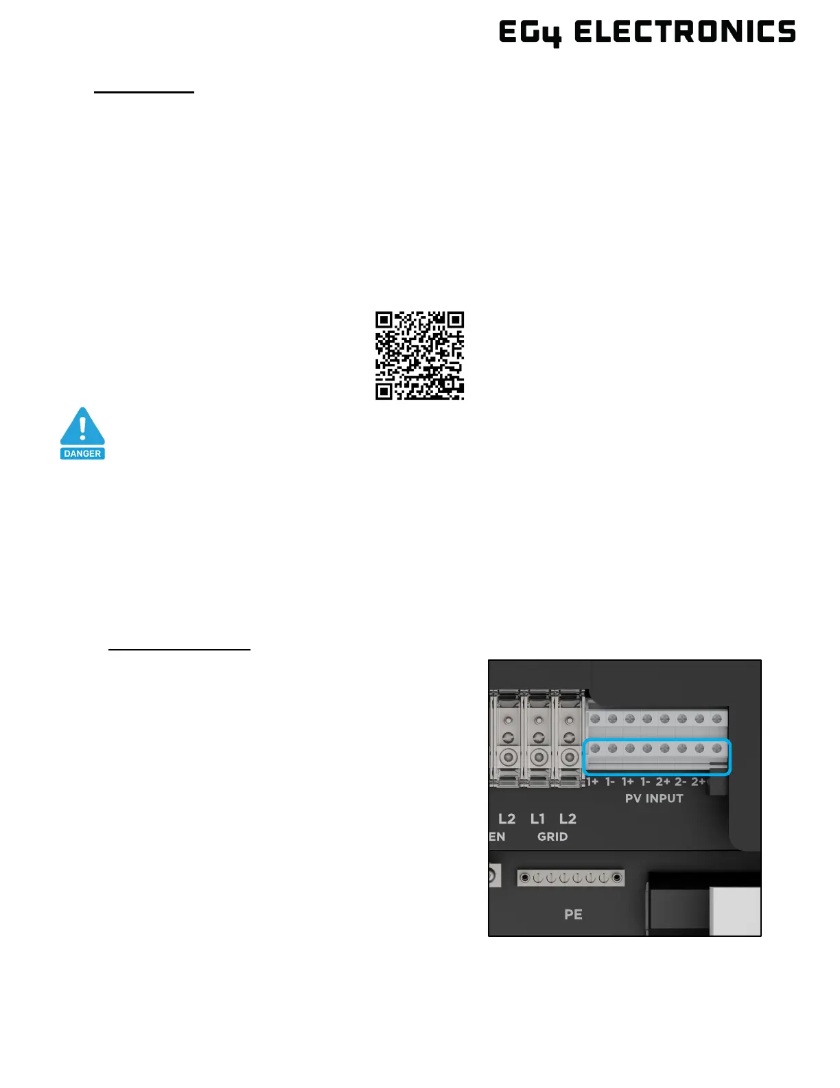
operating range. It is recommended to use the EG4
®
Solar String Sizer by scanning the QR code
below and consult a solar designer for assistance.
All panels in a series/parallel string should face the same orientation and be exposed to roughly the
same shading across the string. Consideration should be placed on string location and wiring order
on the racking to minimize shading effects. One shaded module can disproportionately reduce
output for the entire string. This is because shading on a solar module will cause a drop in voltage.
All panels in a string will drop to match the lowest voltage experienced in any module. Using
Optimizers and/or use string geometries that account for how the shading patterns affect partial
shading of the string.
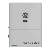
Cable Installation:
1. Before installing PV wiring to the inverter, ensure
all breakers and disconnects are in the open (off)
position. Confirm each PV string (negative and
positive wire pair) has no DC voltage using a
multimeter. Once verified, continue to step 2.
2. Strip off 1/4 – 5/16 in. (6 – 8 mm) insulation from
the PV strings’ positive and negative wires. When
using fine stranded wire, use ferrules to secure the
connections to the inverter.
3. Route the PV wire through the knockouts and into
the inverter.
4. Secure the PV wiring in place into their respective
terminals and torque to 10.6 in-lbs. (1.2Nm). Verify
the cables are secure by lightly tugging on them.
5. Ensure the conduit is fastened reliably, and the
cable entry holes are sealed.
6. Once cabled, each MPPT controller must be configured as single or combined on the LCD
display panel or in the Monitor Center (see step 9 in section 7.1 to configure the MPPTs).
DANGER:
Damage WILL occur if the string voltage exceeds the inverter’s maximum input
voltage of 480VDC! All string sizing calculations should be performed using a
sizing calculator or by consulting a solar professional designer/installer.