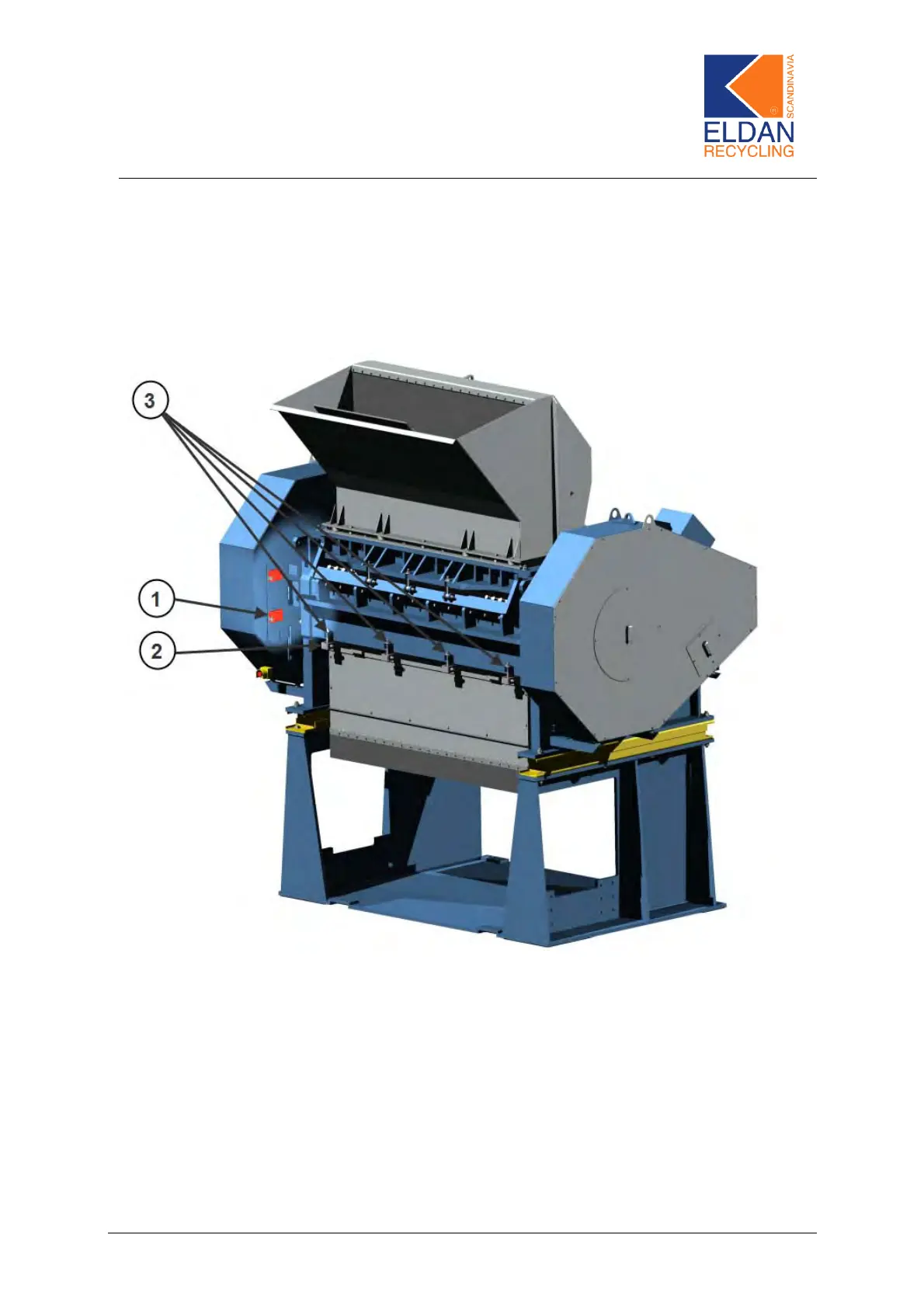
6.11 Removing the discharge hopper and the screen
Figure 11
1) Release the safety switch, Figure 11 – Pos. 1, before removing the front
plate.
2) Remove the retaining bolts, Figure 11 – Pos. 2, using a 17-mm spanner
and remove the front plate.
3) The 4 eyebolts, Figure 11 – Pos. 3, are loosened.
4) Turn on the hydraulic motor by tu rning on the start/st op button on the con-
trol panel.
5) The screen holder, Figure 12 – Pos. 1, can now be lowered by means of
the hydraulic control handle, which is placed on the side of the machine.
ELDAN Recycling A/S Page 37