57
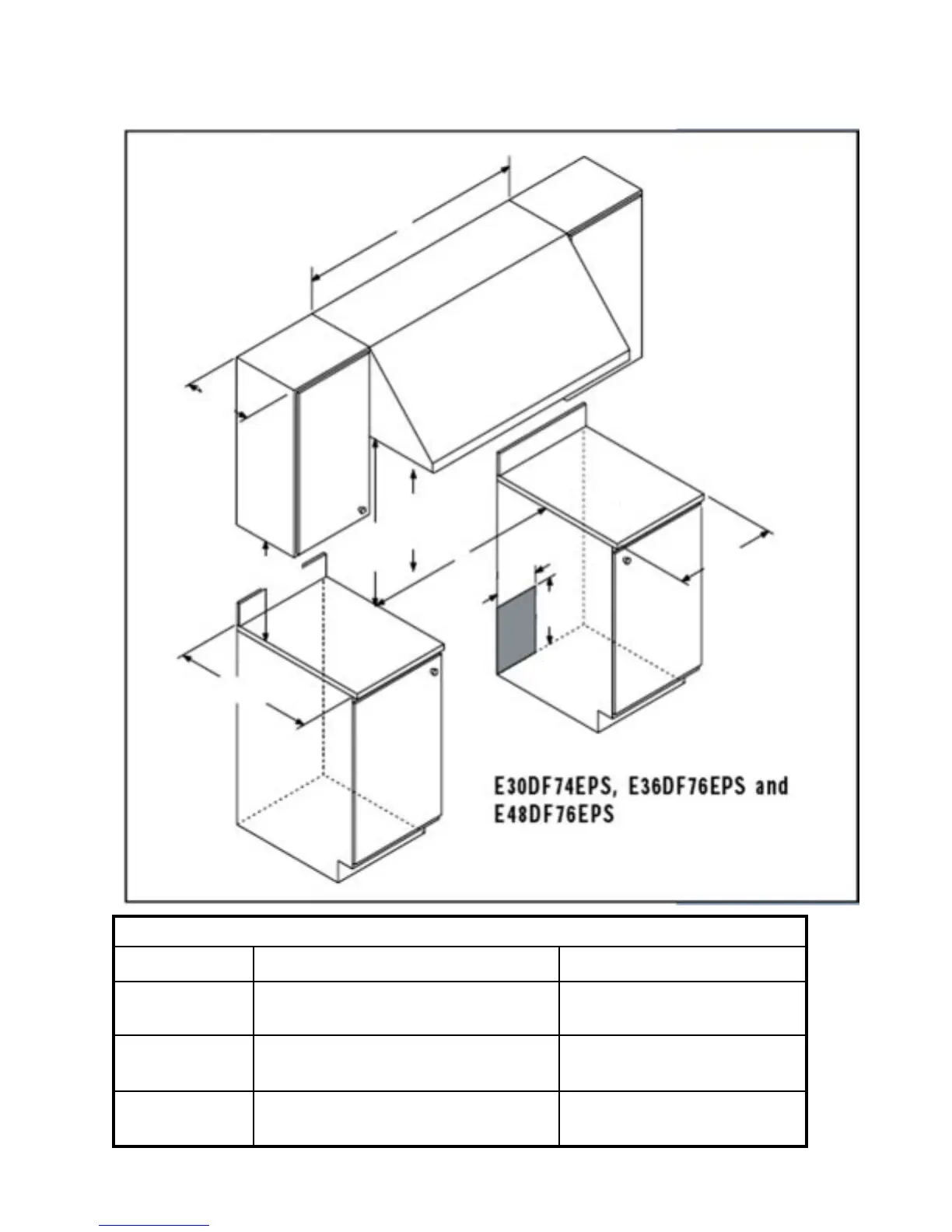
Plan the installation so that the electrical connection, gas shut-off valve, and pressure regulator are accessible
from the front of the cabinet.
Cutout Dimensions
Model “A” “B”
E30DF74EPS 36” (914mm) Recommended 30 1/16” (764mm)
30” (762mm) Minimum
E36DF76EPS 42” (1067mm) Recommended 36 1/16” (914mm)
36” (914mm) Minimum
E48DF76EPS 54” (1372mm) Recommended 48 1/8” (1222mm)
48” (1219mm) Minimum
A
13”
(330mm)
Maximum
Hood
B
Top of
finished
counter
25”
(635mm)
18” (457mm)
minumin
30” (762mm)
minumin
Vertical
non-combustible
Surface
8”
(203mm)
12”
(305mm)
10” (254mm) Min.
to combustible side
wall above the renge
(both sides)