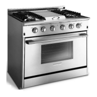
74
burner igniter’s each. If the range has six top burners
Ib1 would represent three igniters and Ib2 would repre-
sent three igniters. The resistor R1is placed in the cir-
cuit to slow down the charging time and control the num-
ber of sparks per second.
Once the burner has been ignited the module monitors
the flames present by sending a small electrical signal
to the igniter for that burner. A gas flame will conduct
an electrical current. The electrical signal, sent by the
module to the igniter, passes through the gas flame to
the burner head. From the burner head the signal
passes into the range chassis and returns to the mod-
ule through the ground terminal on the module. This
tells the module that flame is present on the burner. If
for any reason the flame goes out, the circuit is inter-
rupted. This tells the module to power the charging cir-
cuit and reignite the burner.
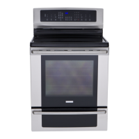
Oven Operation
The oven system is made up of; the electronic oven
control board mounted between the burner box and the
top of the oven,
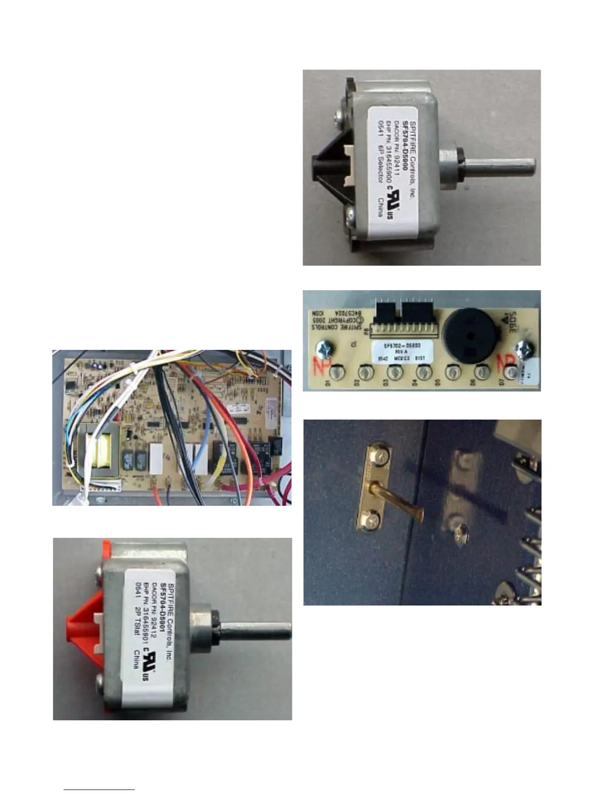
temperature selector mounted to the console,
function selector mounted to the console,
interface board mounted to the console,
oven sensor mounted to the rear wall of the oven,