For clarity Figure 20 on page 37 shows the inner rail without the server attached.
Figure 20 Aligning the inner rail with white plastic guide block
3. Slide the server into the cabinet so the inner rails extends over the plastic guide
blocks and the first part of the ball bearing retainer assemblies (Figure 21 on page
37).
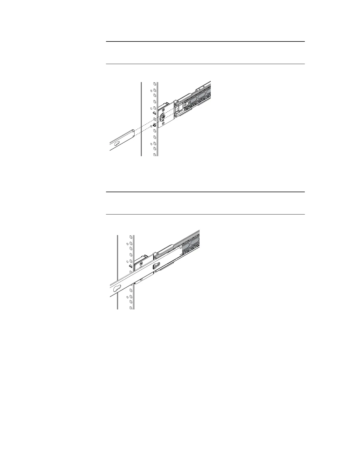
For clarity Figure 21 on page 37 shows the inner rail without the server attached.
Figure 21 Inner rail over the first part of ball bearing retainer assembly
4. Once the inner rails are properly engaged with the ball bearing retainer assemblies,
push the server into the cabinet until the slide rails are engaged and locked.
An audible click indicates that the slide rails are engaged and locked.
5. On the outside of each rail assembly, slide the blue disconnect tab forward to unlock
the server, and push the server completely into the cabinet (Figure 22 on page 38).
Assemble components in your cabinet
Install Control Stations and the extension cables 37

 Loading...


