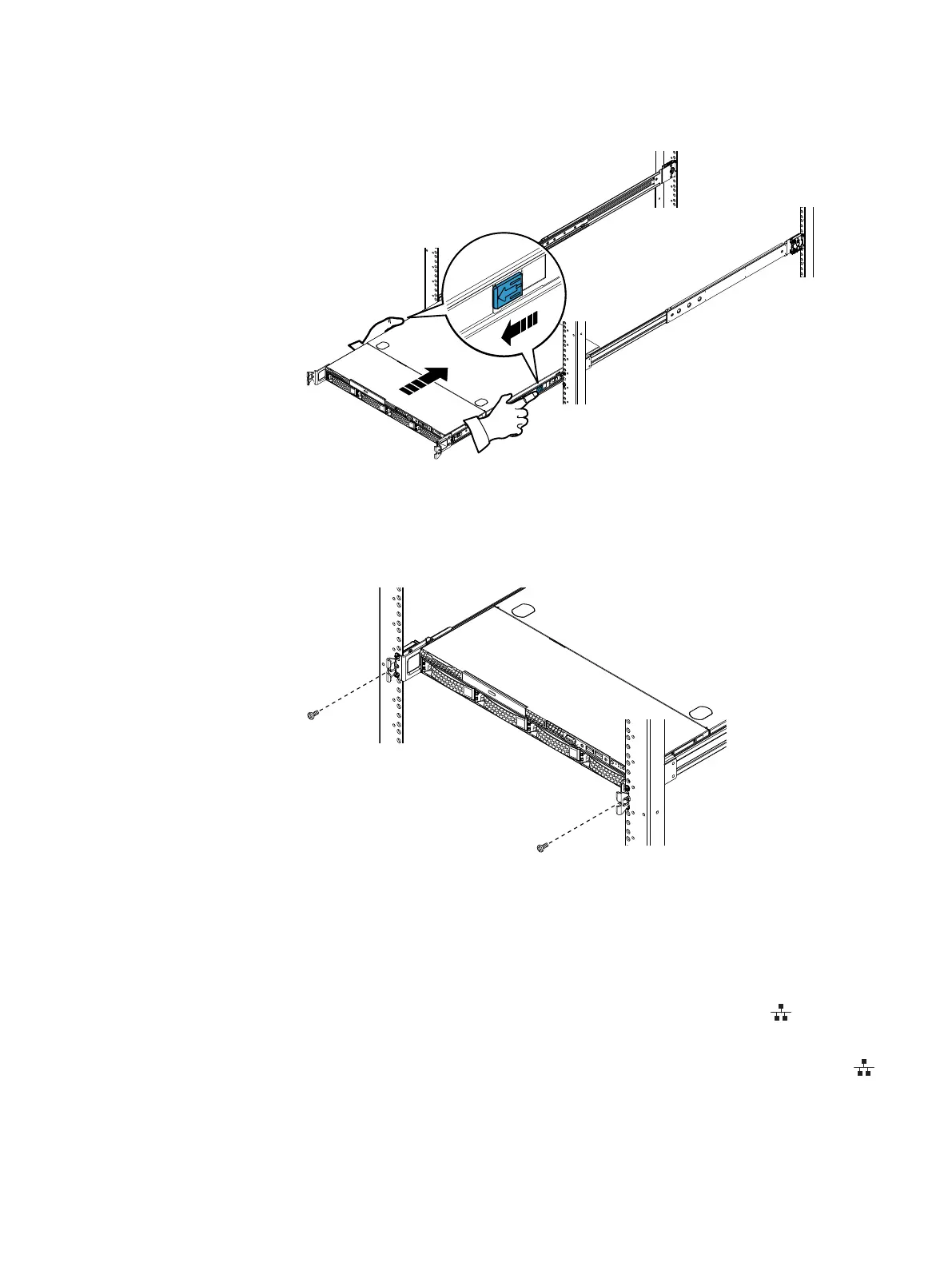
Figure 22 Inserting the server in the cabinet
6. To further secure the rail assembly and server in the cabinet, insert and tighten a
small stabilizer screw directly behind each bezel latch (Figure 23 on page 38).
Figure 23 Installing the stabilizer screws
Connect Control Station extension cables
Procedure
1. Connect the CS0 extension cables. Refer to Figure 24 on page 39. Extension cables
are labeled CS0.
a.
Connect the CS0 B extension cable to the RJ-45 connector, labeled
on the CS
(see cable 1).
b.
Connect the CS0 MGMT extension cable to the RJ-45 connector, labeled
on the CS (see cable 2).
Assemble components in your cabinet
38 EMC VNX Series VNX5600 Unified Installation Guide

 Loading...


