EasyManuals Logo

EMC VNX Series Installation Guide

EMC VNX Series
92 pages
To Next Page IconTo Next Page
To Previous Page IconTo Previous Page
Page #39 background imageLoading...
Page #39 background image
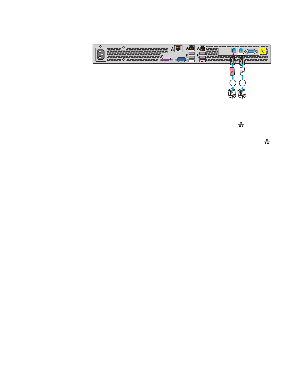
Figure 24 Installing the Control Station extension cables
B MGMT
MGMT
B
CS
A
1
2
MGMT
IOIO
1
2
2. If a secondary Control Station (CS1) is shipped with the order, connect the CS1
extension cables. Extension cables are labeled CS1.
a.
Connect the CS1 B extension cable to the RJ-45 connector, labeled
B
on the CS
(see cable 1 in Figure 24 on page 39).
b.
Connect the CS1 MGMT extension cable to the RJ-45 connector, labeled
MGMT
on the CS (see cable 2).
Assemble components in your cabinet
Install Control Stations and the extension cables 39

Table of Contents

Other manuals for EMC VNX Series

Questions and Answers:

Question and Answer IconNeed help?

Do you have a question about the EMC VNX Series and is the answer not in the manual?

EMC VNX Series Specifications

General IconGeneral
Management InterfaceUnisphere
Drive SupportSAS, NL-SAS, Flash (SSD)
RAID LevelsRAID 0, 1, 3, 5, 6
Protocols SupportedFibre Channel, iSCSI, NFS, CIFS
Data ServicesDeduplication, Compression, Snapshots, Replication
ProcessorIntel Xeon
Operating SystemVNX Operating Environment (block), VNX File Operating Environment (file)

Related product manuals