14 Chapter 3 Installation and Wiring
PB
P(+)
L
N
L
N
singl e phase
power supply
50/60Hz
IM
X
1
X
2
X
3
X
4
X
5
CD
multi-functional
terminal 1
multi-functional
terminal 2
multi-functional
terminal 3
multi-functional
terminal 4
multi-functional
terminal 5
P24
U
V
W
PE
.
(—)
MCCB
multi-functional
terminal 6
multi-functional
terminal 7
COM
X
6
X
7
OD
OD command
input
CD command
input
PC1 is defined as a relay
for completely- OD:
* Not completely, PAC-
PC1 open
Completely, PAC-PC1
closed
PC2 is defined as a relay
for completely- CD:
* Not completely, PAC-
PC2 open
Completely, PAC-PC2
closed
PB
PC
PA
PC1
PAC
PC2
PG power
so urc e
auxiliary
power
source
main control board
defined as fault relay
defaultly:
* Normal,PA-PB
closed
Fault,PA-PC
closed
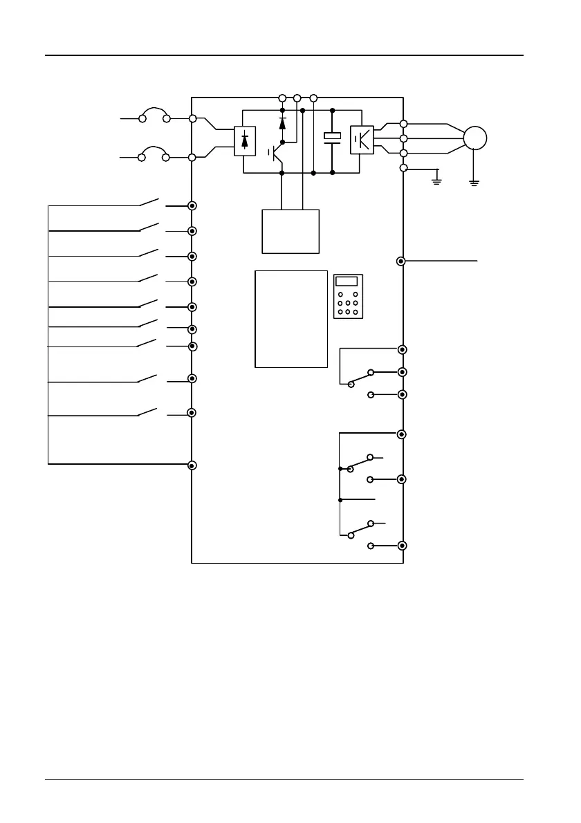
Figure 3-5 Basic Wiring
TD3200 can be fed two kinds of PG signal, and provide only 24V power
supply to PG.
1. The wiring of the open-collector PG with 24V power supply is shown in
Figure 3-6.
TD3200 Variable Speed Drive for Elevator Door Control User Manual
 Loading...