10 Chapter 3 Installation and Wiring
Chapter 3 Installation and Wiring
3.1 Unpacking Inspection
Upon unpacking, please confirm the following:
Any damage occurred during transportation;
Check whether the rated values on the nameplate of the drive are in
accordance with your order.
If there is anything missed, please contact us or the your supplier.
3.2 Installation
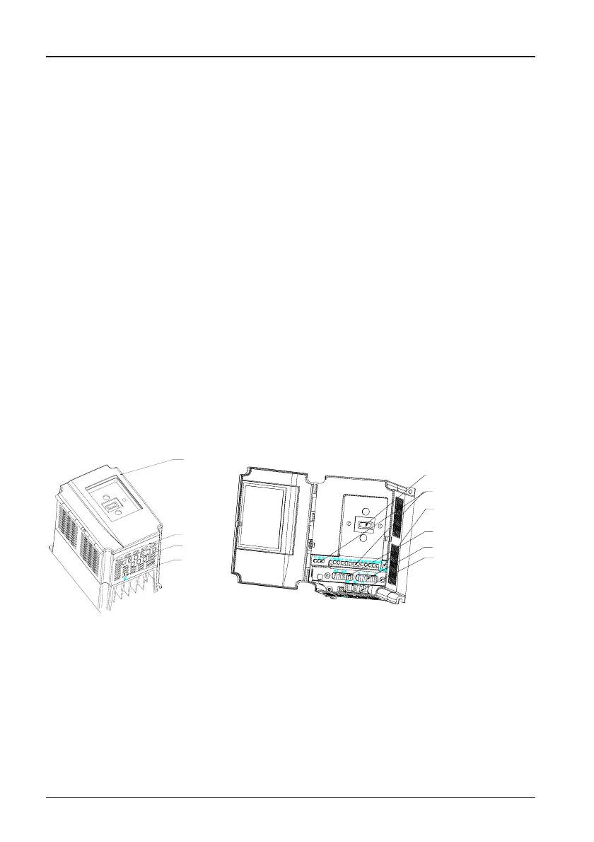
The structure of TD3200 series drive is shown in Figure 3-1 and its
dimensions are shown in Figure 3-2 and Table 3-1.
The drive should be installed vertically. The clearance requirements are
shown in Figure 3-3 and Figure 3-4.
cover
control terminal
cable input port
of main circuit
earthing point
control terminal
cable input port
of main circuit
earthing point
control terminal
keypad or
status display unit
jumpers
CN9,
CN10
AC supply
L,N
output
U,V,W
DC bus and braking terminal
P(+),PB,(-)
control terminal
keypad or
status display unit
jumpers
CN9,
CN10
AC supply
L,N
output
U,V,W
DC bus and braking terminal
P(+),PB,(-)
Figure 3-1 Structure of the drive
TD3200 Variable Speed Drive for Elevator Door Control User Manual
 Loading...