Chapter 7 Application Guidance 79
Chapter 7 Application Guidance
This chapter introduces the basic procedures and parameter setting methods
for the elevator door control system using TD3200 series drive. Applications
of speed control 1 and distance control are introduced below, including the
system Configuration and parameter settings.
7.1 Speed control 1
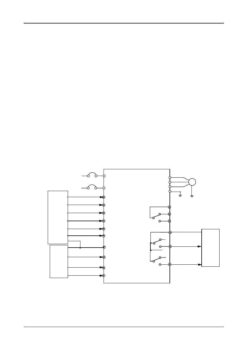
7.1.1 System Wiring Diagram
In speed control 1, speed changing contacts are used to change the speed,
and the location limiting signal is used to judge whether the door is opened or
closed completely. System wiring diagram for speed control 1 is shown in
Figure 7-1.
L
N
Single-phase
AC supply
50/60Hz
IM
X
1
X
2
X
3
X
4
X
5
CD
U
V
W
PE
MCCB
Fault relay
External reset signal
X
6
X
7
OD
OD command
CD command
Complete OD relay
output
Complet CD relay
output
to EARTH of
control system
OD speed
changing NO input
CD speed changing
NO input
OD location
limiting NO input
CD location limiting
NO input
optic signal NO
input
touch board signal
NO input
COM
Elevator
door
mechanical
system
Control
system
Control
system
TD3200 drive
PB
PC
PA
PC2
PAC
PC1
Figure 7-1 System wiring diagram for speed control 1
Note: "NO" in Figure7-1 stands for "normally open" .
TD3200 Variable Speed Drive for Elevator Door Control User Manual
 Loading...