Chapter 7 Application Guidance 85
7) Switch on the drive again, it will operate according to the preset speed of
F005, and the drive will be in stopping status after the door is completely
closed.
8) Set relevant parameters according to table 7-2, and the CD/OD
parameters can be set according to the OD operation curve shown in Figure
6-9 and the CD operation curve shown in Figure 6-10.
9) After testing, set F002 to "1" (terminal control mode), and the drive can
work normally.
7.2.3 Parameters Setting
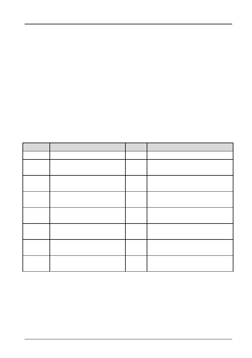
Please refer to Table 7-2.
Table 7-2 Parameter settings for Speed control
Functions Name Setting Remark
F001 Control mode 2 Distance control 1
F097
Function of digital input
terminal X1
10 Phase A PG signal input
F098
Function of digital input
terminal X2
11 Phase B PG signal input
F101
Function of digital input
terminal X5
2
Normally open input contacts for
optic signal
F102
Function of digital input
terminal X6
4
Normally open input contacts for
touch board
F103
Function of digital input
terminal X7
1
External reset (RESET) signal
input
F105
Programmable relay
PAC/PC1
2 Output signal for complete OD1
F106
Programmable relay
PAC/PC2
3 Output signal for complete CD1
TD3200 Variable Speed Drive for Elevator Door Control User Manual
 Loading...