66 Chapter 6 Parameter Descriptions
Note
The drive will not reset automatically when E024, E028, E029 and E030 faults occur.
F084 Utility rate of braking
Range: 0~7
【
7
】
Relationship of settings and utility rate is shown below.
Setting 0 1 2 3 4 5 6 7
Meaning
No dynamic
braking
2% 5% 10% 20% 50% 80% 100%
F085 Reserved
F086 Reserved
6.8 Vector Control Parameters
F087 Display selection for F087~F095
Range: 0, 1
【
0
】
F087 decides whether to display F088~F095.
0: Not display
1: Display
F088 Speed regulator's proportional gain 1
Range: 0.000~6.000
【
1.000
】
F089 Speed regulator's integral time 1
Range: 0, 0.032~32.00s
【
1.000
】
F090 Speed regulator's proportional gain 2
Range: 0.000~6.000
【
1.200
】
F091 Speed regulator's integral time 2
Range: 0, 0.032~32.00s
【
0.400
】
F092 Speed regulator's changing frequency
Range: 0.00~400.00Hz
【
5.00
】
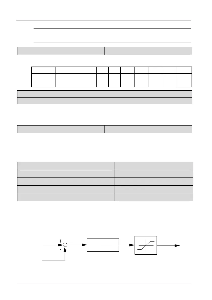
Speed regulator's proportional gain P and integral time I can be set via
F088 ~F092 to change the speed response of vector control.
1. Structure of speed regulator (ASR) is shown in Figure 6-13, where K
p is
proportional gain P, and KI is integral time I.
Frequency
Instruction
Actual
Speed
Reference
Torque Current
+
Speed
Error
Torque Limit
(F3.08,F3.07)
K
p
(1+ )
1
K
I
S
-
Figure 6-13 Simplified speed regulator diagram
TD3200 Variable Speed Drive for Elevator Door Control User Manual
 Loading...