Chapter 6 Parameter Descriptions 67
If the integral time is set at 0 (F089=0, F091=0), which means integral
function is disabled, and the speed loop is simply a proportion regulator.
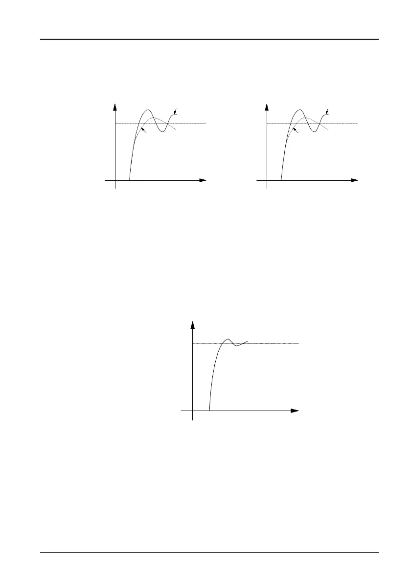
2. Adjustment of proportional gain P and integral time I for speed regulator
Instructed
Speed
Bigger Proportional Gain
Smaller Proportional Gain
Instructed
Speed
Shorter Integral Time
Longer Integral Time
Figure 6-14 Relationship of speed regulator's step response to values of P
and I
Increasing P will fasten system transient response, but system oscillation
may occur given too big P.
Decreasing I will fasten transient response, but system oscillation and
overshoot may occur given too small.
Normally, you may tune P first, increase its value as long as no system
oscillation occurs; then adjust I, ensuring fast response without overshoot.
Figure 6-15 shows better speed step response if P, I are set properly.
Instructed
Speed
Figure 6-15 Step response with better dynamic performance
3. Speed regulator's P, I Settings in High/Low Speed Applications
If the system is required to respond quickly both in low and high frequency
operation with load and, then the user may set speed regulator's switching
frequency in F092. Normally, when the system runs at low frequency, the
transient response performance can be improved by increasing P and
decreasing I.
Adjust speed regulator's parameters following the procedures below:
TD3200 Variable Speed Drive for Elevator Door Control User Manual
 Loading...