Chapter 7 Application Guidance 83
Functions Name Setting Remark
F082
Carrier frequency
adjustment
8k Set according to system requirements
F084 Utility rate of braking 7
Set properly according to braking
condition
Attention
F006 must be set bigger than the sum of time in all phases of CD or OD curve.
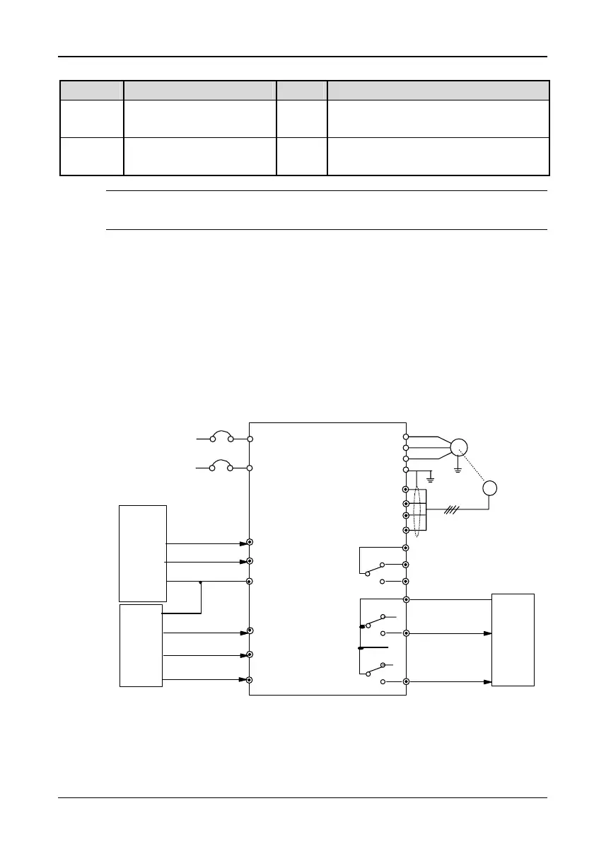
7.2 Distance Control 1
7.2.1 System Wiring Diagram
For distance control 1, PG should be installed on the motor's shaft. In
distance control, the speed changing and complete CD and OD judgments
are made according to the actual number of pulses counted. System wiring
diagram for distance control is shown in Figure 7-2.
MCCB
L
N
M
X
1
X2
X
5
CD
U
V
W
PE
PB
PC
PA
COM
X
6
X
7
OD
PG
COM
P24
PG: Pulse
generator
PC1
PAC
PC2
Fault relay
Control
system
Control
system
Elevator
door
mechanical
system
Single-phase
AC supply
50/60Hz
TD3200 drive
optic signal NO
input
touch board signal
NO input
External reset signal
OD command
CD command
Completly OD
relay output
Complete CD relay
output
to EARTH of
control system
Figure 7-2 System wiring diagram for distance control
TD3200 Variable Speed Drive for Elevator Door Control User Manual
 Loading...